
User Manual


LOW VOLTAGE WIRE SIZE CHART
2
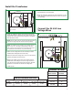
Install the Transformer
1: Select the location between the wall studs (16" apart) where
the transformer is to be mounted.
2: Place the transformer between the studs and fasten it to the
studs through the bracket holes with four #8 or #10 screws
(not provided).
A
STUD
COM T2
T3
T4T1
SCREW
BRACKET
2
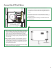
Connect the 24 Volt Low
Voltage Wires
B
1: Install two THHN low voltage wires from the transformer
to the electrical box to which the power feed canopy will be
attached. Run the proper size wire using the "Low Voltage
Wire Size Chart" below.
2: Insert one low voltage wire into the secondary terminal
marked "COM" and tighten the screw firmly.
3: Insert the second low voltage wire to the "T2" tap terminal
(default) and tighten the screw firmly.
4: Measure the voltage at the power wires coming into the
transformer. If the voltage is not in the range of 250-277
volt, then pick the proper terminal tap using the "Terminal
Tap Chart" to reconnect the second low voltage wire.
5: Install drywall.
COM
T3
T4T1
2
3
1
LOW VOLTAGE WIRES
TRANSFORMER
WATTAGE
WIRE SIZE
FOR 5 FT
WIRE SIZE
FOR 6-15 FT
WIRE SIZE
FOR 16-20 FT
WIRE SIZE
FOR 21-40 FT
600 WATT #12 GA #8 GA #6 GA #4 GA
NOTE: The THHN wire sizes specified in "Low Voltage Wire Size
Chart" are for 3% or less drop in voltage based on 600 watt
loads. Lengths are the distance from the recessed transformer to
the system power feed connector, or power feed canopy.
T2
TERMINAL TAP CHART
PRIMARY POWER
INPUT VOLTAGE
TERMINAL TAP
TO BE USED
220-229
230-249
250-277
278-285
T4
T3
T2
T1
ELECTRICAL BOX
NOTE: Using a smaller wire size other than specified will result in
a increase in voltage drop and will reduce the lamp intensity.