
Instruction Manual

C
COM T1 T2 T3 T4
CONDUIT
12
3
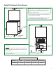
7: Install a conduit from the transformer to the electrical box.
8: For the best performance, use the "Low Voltage Wire Size
Chart" on page 2 to select the wire size.
NOTE: Smaller wires sizes than specified will result in an increase
voltage drop and will reduce the lamp intensity.
ELECTRICAL BOX
13
9
9
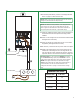
NOTE: The THHN wire sizes specified in "Low Voltage Wire Size
Chart" are for 3% or less drop in voltage based on 300 watt
loads. Lengths are the distance from the remote transformer to
the system power feed connector, or power feed canopy.
9: Install the THHN low voltage wires from the transformer to
the electrical box where the power feed canopy will be
installed.
10: Insert one low voltage wire into the terminal marked "COM"
and tighten the screw firmly.
11: Insert the second low voltage wire into the "T2" terminal
tap (default) and tighten the screw firmly.
12: At this time, connect the 230 volt power wires at the panel.
13: Measure the voltage at the power wires coming into the
transformer. If the voltage is not in the range of 201-220
volt, then pick the proper terminal tap using the "Terminal
Tap Chart" below to reconnect the second low voltage wire.
TERMINAL TAP CHART
PRIMARY POWER
INPUT VOLTAGE
TERMINAL TAP
TO BE USED
175-183 T4
184-200
201-220
221-225
T3
T2
T1
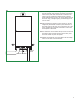
NOTE: Risk of Fire - The terminal taps ARE NOT for boosting
the transformer low voltage power, they are selected to ensure
output power voltage based upon input power voltage condition.
NEVER use a higher terminal tap to compensate for voltage
drop, this will overheat the low voltage wires and transformer. It
is recommended to use the wire size as indicated in "Low
Voltage Wire Size Chart" on page 2 to avoid excessive voltage
drop.
10
11
7