
Installation guide


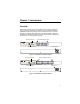
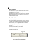
Table Of Contents
- Chapter 1: Introduction
- Chapter 2: Network Planning
- Chapter 3: Installing the Switch
- Chapter 4: Making Network Connections
- Appendix A: Troubleshooting
- Appendix B: Cables
- Appendix C: Specifications
- Appendix D: German Instructions
- Glossary
- Index

xii
Figures
Figure 1-1. ES4016 Front and Rear Panels 1-1
Figure 1-2. ES4024 Front and Rear Panels 1-1
Figure 1-3. ES4016 Port and System Status LEDs 1-2
Figure 1-4. ES4024 Port and System Status LEDs 1-3
Figure 1-5. ES4016/ES4024 Power Supply Socket 1-3
Figure 2-1. Collapsed Backbone 2-2
Figure 2-2. Network Aggregation Plan 2-3
Figure 3-1. RJ-45 Connections 3-2
Figure 3-2. Attaching the Brackets 3-3
Figure 3-3. Installing the Switch in a Rack 3-4
Figure 3-4. Attaching the Adhesive Feet 3-4
Figure 3-5. Power Socket 3-5
Figure 4-1. Making Twisted-Pair Connections 4-1
Figure 4-2. Network Wiring Connections 4-2
Figure B-1. RJ-45 Connector Pin Numbers B-1
Figure B-2. Straight-through Wiring B-2
Figure B-3. Crossover Wiring B-3