
Installation guide


C
HAPTER
1
| Introduction
Description of Hardware
– 26 –
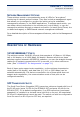
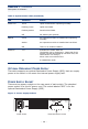
10 GIGABIT ETHERNET MODULE SLOTS
These switches include two slots on the rear panel for hot-swappable single-port
10GBASE modules with XFP transceivers. Refer to “Optional Media Extender
Modules” on page 29 for more information on this module and the supported
10G transceivers.
STACKING PORTS
Each unit includes two stacking ports that provide a 48 Gbps high-speed serial
stack backplane connection. Up to eight 24-port or 48-port switches can be
connected together using optional stacking cables. Note that the 24-port and
48-port switches can be mixed in the same stack. The Stack Master button
enables one switch in the stack to be selected as the Master unit for managing
the entire stack.
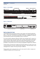
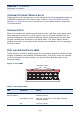
PORT AND SYSTEM STATUS LEDS
These switches include a display panel for key system and port indications that
simplify installation and network troubleshooting. The LEDs, which are located
on the front panel for easy viewing, are shown below and described in the
following tables.
Figure 3: Port LEDs
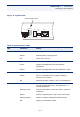
Table 1: Port Status LEDs
LED Condition Status
Link/
Activity/Speed
On/Flashing Amber Port has a valid link at 10 or 100 Mbps. Flashing
indicates activity.
On/Flashing Green Port has a valid link at 1000 Mbps. Flashing
indicates activity.
Off The link is down.
Port Status LEDs
1
2
3
4
5
6
7
8910
11
12
13
14
15