
Installation guide


– 21 –
FIGURES
Figure 1: Front Panels 24
Figure 2: Rear Panel 24
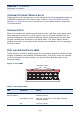
Figure 3: Port LEDs 26
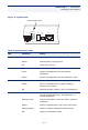
Figure 4: System LEDs 27
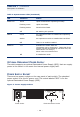
Figure 5: Power Supply Sockets 28
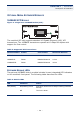
Figure 6: Single-Port 10GBASE Module (XFP) 29
Figure 7: Collapsed Backbone 34
Figure 8: Network Aggregation Plan 35
Figure 9: Remote Connections with Fiber Cable 36
Figure 10: Making VLAN Connections 37
Figure 11: IP Routing for Unicast Traffi 38
Figure 12: RJ-45 Connections 42
Figure 13: Attaching the Brackets 45
Figure 14: Installing the Switch in a Rack 45
Figure 15: Attaching the Adhesive Feet 46
Figure 16: Installing an Optional Module 47
Figure 17: Inserting an SFP Transceiver into a Slot 48
Figure 18: Making Stacking Connections 50
Figure 19: Power Socket 51
Figure 20: Serial Port (RJ-45) Pin-Out 52
Figure 21: Making Twisted-Pair Connections 56
Figure 22: Network Wiring Connections 58
Figure 23: Making Fiber Port Connections 59
Figure 24: Connecting to an XFP Transceiver 62
Figure 25: RJ-45 Connector Pin Numbers 71
Figure 26: Straight-through Wiring 73
Figure 27: Crossover Wiring 73