
Installation guide


– 21 –
FIGURES
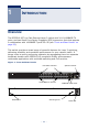
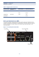
Figure 1: Front and Rear Panels 23
Figure 2: Port and System Status LEDs 26
Figure 3: Power Supply Inlet 28
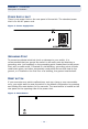
Figure 4: Reset Button 28
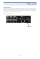
Figure 5: Console Port 29
Figure 6: Collapsed Backbone 32
Figure 7: Network Aggregation Plan 33
Figure 8: Remote Connections with Fiber Cable 34
Figure 9: Making VLAN Connections 35
Figure 10: RJ-45 Connections 38
Figure 11: Grounding 40
Figure 12: Attaching the Brackets 41
Figure 13: Installing the Switch in a Rack 42
Figure 14: Attaching the Adhesive Feet 43
Figure 15: Inserting an SFP Transceiver into a Slot 44
Figure 16: Power Inlet 45
Figure 17: Console Cable 46
Figure 18: Making Twisted-Pair Connections 50
Figure 19: Network Wiring Connections 51
Figure 20: Making Fiber Port Connections 53
Figure 21: RJ-45 Connector Pin Numbers 59
Figure 22: Straight-through Wiring 61
Figure 23: Crossover Wiring 61