
Installation manual


©2014 Edelbrock LLC
Part #1596, 1597, 1598, 1599
Brochure #63-1598
Rev. 9/19/14 - QT/mc
Edelbrock E-Force Supercharger System
2010-2014 Camaro SS
Installation Instructions
Page 22
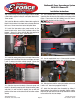
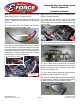
137. Apply o-ring lube to the upper seals of the supplied
fuel injectors and install them into the supplied fuel rails
so that the electrical connectors are oriented towards the
rounded side of the rails.
138. Lower the passenger fuel rail assembly onto the
manifold lining up the injectors with their provisions on the
manifold. Gently, push down on the rails until the injectors
are fully seated. Secure fuel rail using a 5mm Hex tool and
two (2) M6 x 12mm bolts from Bag #3.
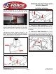
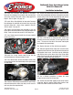
139. Install the supplied Fuel Rail Inlet between the EVAP
fitting and fuel rail fitting on the passenger side. DO NOT
install this fuel input line onto the smaller 8mm barb meant
for the EVAP.
140. Install the supplied Brake Booster to Manifold Hose
onto the brake booster fitting and secure it with the 3/4”
hose clamp supplied in Bag #2. Then connect the other
end of the brake booster hose to the fitting on the driver
side of the supercharger air inlet and secure it with another
3/4” hose clamp supplied in Bag #2.
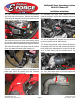
141. Connect the supplied Fuel Rail Crossover line with the
90° fittings to the passenger side fuel rail. Route the
crossover line below the hub snout and air inlet of the
supercharger and over to the front of the driver side rail.
Clip the Fuel Rail Crossover line onto the driver side fuel rail
fitting.
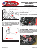
142. Reattach the fuel injector electrical connectors.
143. Install the 90° end of the Manifold to EVAP Solenoid
Hose to the fitting directly below the supercharger snout.
Route the other end of the hose under the EVAP solenoid
and connect it to the grey barb on the EVAP solenoid.
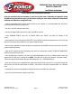
144. Connect the 90° end of the EVAP Solenoid to EVAP
Hard Line Hose to the black barb on the EVAP Solenoid (side
with connector). Route the hose back over the passenger
side coils and connect to the EVAP hard line. DO NOT
confuse the 10mm fuel output line with the 8mm EVAP line.
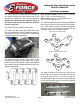
145. Use a 10mm wrench to remove the valve cover ball
stud from the driver side valve cover (if applicable).
146. Use a pair of pliers to remove the vacuum cap from
the rear of the driver side valve cover (if applicable).