
Installation manual


©2014 Edelbrock LLC
Part #1596, 1597, 1598, 1599
Brochure #63-1598
Rev. 9/19/14 - QT/mc
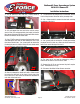
Edelbrock E-Force Supercharger System
2010-2014 Camaro SS
Installation Instructions
Page 17
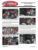
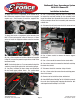
91. Use a breaker bar and a 24mm socket to loosen and
remove the crank bolt. A long pipe slid over the breaker bar
can be helpful for increasing leverage.
92. Install the drill guide and the M16 x 120mm bolt supplied
in Bag #4 onto the end of the crankshaft.
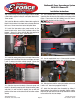
93. Measure 1.7” from the tip of the 15/64” drill bit supplied
in Bag #4 and mark the position with a piece of masking
tape then drill into the crank through the hole in the guide
that has a bushing in it until the tape mark reaches the drill
guide.
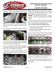
94. Loosen the bolt holding the drill guide and rotate it until
the second hole lines up with the hole drilled in the crank.
Use the back side of the ream tool to verify the guide is
correctly aligned.
95. Tighten the guide bolt then use compressed air to clean
out any metal flakes in the drill hole.
96. Insert the supplied ream tool through the hole and ream
the full depth of the hole.
97. Use compressed air to clean out any metal flakes then
loosen the bolt and remove the drill guide.
98. Apply red Loctite retaining compound to the supplied
crank pin and tap it into the reamed hole until it is flush with
the crank snout.
99. Install the crank bolt supplied in Bag #4 and torque it to
37 ft-lbs then rotate it an additional 140°.
100. Remove GM Flywheel Holding Tool #J-42386-A.
101. Lift the starter support bracket and starter into place
then use a 13mm wrench to reinstall the power wire onto
the starter.
102. Reconnect the starter solenoid electrical connector.
103. Use an 8mm wrench to reinstall the three bolts that
hold the starter heat shield in place.
104. Use a 13mm socket to install the two starter bolts.
105. Use a 10mm socket to reinstall the starter support
bracket bolt.
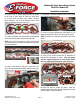
106. Lower the fan assembly back into place, reconnect
the passenger side electrical connector then use a 13mm
socket to reinstall the stock fan assembly bolt on the driver
side only, the passenger side will be installed later.
107. Use a panel puller to remove the two body pins from
the top of the lower radiator shroud.
NOTE: Convertible models are equipped with a brace that
connects the frame extensions, this brace will need to
be removed and replaced with the Edelbrock Convertible
Brace (Part #15956, Sold Separately) as it interferes with
the installation of the Edelbrock heat exchanger.
108. Install the supplied heat exchanger behind the bumper
so that the lower bracket holes line up with those in the
radiator shroud.