
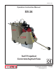
Owner's manual

E-SS24-I-0414
Printed in USA
KMS ©2014
Page 5
100 Thomas Johnson Drive, Frederick, MD 21702-4600 USA
Phone (301) 663-1600 • 1-800-638-3326
Fax (301) 663-1607 • 1-800-447-3326
Website: www.edcoinc.com
Email: sales@edcoinc.com
A Division of Equipment Development Company, Inc.
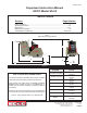
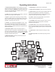
Operating Instructions
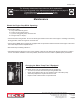
7 - Depth Gauge: Provides readout of blade depth.
8 - Depth Control Handwheel: Raises and lowers the blade.
9 - Speed Control: ControlssawspeedinFWDandREV.This
EDCOsawisequippedwithaHydrostaticTransmission,
whichpermitsinnitespeedcontrol.(Actualcuttingspeedis
limited by the saw blade and cutting conditions).
10 - Clutch: Pull back to engage DRIVE. Push forward to
release drive wheels (Freewheel) SS-24.
11 - Hour Meter: Gives readout of engine run-time. One sug-
gested use for this meter is to keep track of scheduled
maintenance. (See page 11)
12 - Handle Locks: Loosenknobstoadjusthandleposition.
Be sure to securely retighten the knobs once handles are posi-
tioned. Adjust before starting saw for operator comfort and safe
operation.
13 - Guide Rope: Provides raising and lowering of cutting
guide.
14 - Guide Rope Cleat:LocksGuideRopeduringtransitor
storage.
1 - Emergency Stop (E-Stop): Before operation, be sure the
E-Stopisresetbyturning/liftingtheknob.PUSHtoshutoffthe
engine in an emergency. CAUTION: Shut off the ignition when
not in use. UsingtheE-StopasanON/OFFswitchinplaceof
the ignition will drain the battery.
2 - Choke: Use to aid cold weather engine starting. Follow the
instructions in the Engine Owner’s Manual.
3 - Ignition: (Optional location depending on engine model)
Turn key to START position. Once engine starts, leave in RUN
position. Shut off Ignition Switch between uses. As a safety
precaution, remove key when not in use.
4 - Throttle: TurnCOUNTERCLOCKWISEtounlock.PULL
UPtoincreaseengineRPM,PUSHDOWNtodecrease.Turn
CLOCKWISE to lock cable in position once desired engine
speed is reached. For optimum performance engine should be
operated at full RPMs.
5 - Blade Saver Switch: Must be in the DRY position or
engine will not start. The purpose of the Blade Saver is to stop
theengineifwaterpressuredrops.IfusingaWETCUTBlade,
open the water valve and select the WET position after starting
the engine and before starting to cut.
6 - Water Pump Switch: (Optional) Activated pump to pull
water from an external tank.
Figure 2
3
Ignition
5
Blade Saver
Switch
11
Hour
Meter
12
Handle
Locks
10
Clutch
9
Speed
Control
12
Handle
Locks
1
Emergency Stop
(E-Stop)
14
Guide
Rope
Cleat
4
Throttle
13
Guide
Rope
8
Depth
Gauge
7
DepthControl
Handwheel
2
Choke
6
Water Pump
Switch