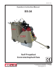
E-SS24-I-0414 Operators Instruction Manual SS-24 Self Propelled Concrete/Asphalt Saw A Division of Equipment Development Company, Inc. 100 Thomas Johnson Drive, Frederick, MD 21702-4600 USA Phone (301) 663-1600 • 1-800-638-3326 Fax (301) 663-1607 • 1-800-447-3326 Website: www.edcoinc.com Email: sales@edcoinc.
E-SS24-I-0414 READ AND UNDERSTAND THE OPERATORS INSTRUCTION MANUAL THOROUGHLY BEFORE ATTEMPTING TO OPERATE THIS EQUIPMENT. Death or serious injury could occur if this machine is used improperly. SAFETY MESSAGES SAFETY MESSAGES • Safety Instructions are proceeded by a graphic alert symbol of DANGER, WARNING, or CAUTION. Indicates an imminent hazard which, if not avoided, will result in death or serious injury. Indicates an imminent hazard which, if not avoided, can result in death or serious injury.
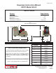
E-SS24-I-0414 Equipment Instruction Manual EDCO Model SS-24 Table of Contents Section Page Number Safety Guidelines..............................................................................................................4 Operating Instructions....................................................................................................5-8 Maintenance.................................................................................................................9-14 Maintenance Schedule.......
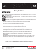
E-SS24-I-0414 Read and understand the Operator’s Manual, the Rx for Concrete Saws, and the Engine Manufacturer’s Owner’s Manual before operating this equipment. Death or serious injury can result if this machine is used improperly. Safety Guidelines Maintain a safe operating distance from flammable materials. Sparks from the cutting-action of this saw can ignite flammable materials or vapors. Operator must wear appropriate clothing and footwear.
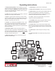
E-SS24-I-0414 Operating Instructions 1 - Emergency Stop (E-Stop): Before operation, be sure the E-Stop is reset by turning/lifting the knob. PUSH to shut off the engine in an emergency. CAUTION: Shut off the ignition when not in use. Using the E-Stop as an ON/OFF switch in place of the ignition will drain the battery. 7 - Depth Gauge: Provides readout of blade depth. 8 - Depth Control Handwheel: Raises and lowers the blade. 9 - Speed Control: Controls saw speed in FWD and REV.
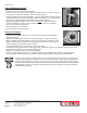
E-SS24-I-0414 Before Starting the Engine: • Read Rx for Concrete Saws before operating. • Inspect machine before each use according to the Maintenance Schedule on page 15. • Locate and be familiar with all engine and saw controls (Figure 2). • Inspect the blades carefully before installing. Use the correct blade for the job. Check rated RPM, diameter and size configuration. Make sure blades are correctly mounted. • For wet cutting, attach supply hose to Water Hook Up Valve (Figure 3).
E-SS24-I-0414 Wet Cutting Only: Maximum Depth of Cut SS-24 for 14” diameter blade........... 4 3/4” for 16” diameter blade........... 5 3/4” for 18” diameter blade........... 6 3/4” for 20” diameter blade........... 7 3/4” for 22” diameter blade........... 8 3/4” for 24” diameter blade........... 9 1/4” For Dry Cutting: Consult Blade Manufacturer for Maximum Depth of Cut. Figure 5 Starting and Controlling the Cut: • • • Engine must be at FULL THROTTLE.
E-SS24-I-0414 To Stop Cutting: • Move Speed Control lever to the NEUTRAL position. • Turn Depth Control Handwheel clockwise until blade is clear of slab. • Push Clutch Lever forward, away from operator to the FREE WHEEL position; this will stop all forward motion. (Page 7, Figure 8) • Return Throttle to idle. • Flip Blade Saver switch back to DRY. • Turn off optional Water Pump then turn off water supply valve. To Stop the Engine: • In an emergency situation, PUSH DOWN the E-Stop.
E-SS24-I-0414 The following maintenance instructions are brief explanations of some of the items suggested in the Maintenance Schedule chart on page 15. These instructions are not replacements for the Engine Manufacturer’s Maintenance Instructions. Maintenance Should the Engine Stop While Operating: • Check water supply: a. Is city water valve fully open? b. Is valve on saw console open? c. If you are using gravity feed, check the flow. d.
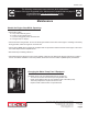
E-SS24-I-0414 Before Changing Blades: Inspect all blades carefully before installing. Check for cracks, loose segments and oversize, worn, or out-of-round arbor holes (See page 13). Do not use any questionable blade since serious personal injury and/or damage to property can result. Do not use warped, twisted, or out-of-balance blades. Unbalanced blades will wear excessively, vibrate and damage both arbor shaft and bearings. For safety reasons, EDCO does not recommend the use of any abrasive blades.
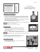
E-SS24-I-0414 (Left side not shown) Important! Arbor Shaft Bearings MUST be lubricated EVERY FOUR HOURS! Drive Axle Bearings (2) Grease Bearings - (7 Total) Arbor Shaft Bearings (2) must be greased every 4 hours. All other Bearings (5) must be greased every 40 hours. Those include: Rear Wheel Bearings (2), Drive Axle Bearings (2), and the Depth Control Handle Wheel Bearing (1).
E-SS24-I-0414 Check Engine Oil Before Each Operation - Check Engine Manufacturer’s Owner’s Manual for specific instructions. Change Oil & Filter Every 50 Hours of Operation (Sooner if Necessary). Check Drive Chains Before Operation Lubricate Weekly Remove the maintenance door at the rear of the machine. Drive chain is just inside in the center of the machine.
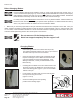
E-SS24-I-0414 Changing To Left-Side Cutting: • Disconnect water hose from the blade guard. • Using SAE 9/16” and 3/4” wrenches, remove the bolts on the blade guard. • On the other side of the machine, remove the arbor guard. • You will have to reroute the water hose to the other side of the engine. It may be necessary to pull the hose back through the hole in the main body of the machine and allow it to run directly up the left side.
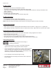
E-SS24-I-0414 Inspect and Replace Air Filter Element If Dirty (Shown with Honda Engine) Replace when necessary with factory parts. Refer to the Engine Manufacturer’s Owner’s Manual for specific requirements. Air Filter Transmission Fluid Inspect Transmission Fluid Level Every 50 hours of operation - fill as required. The fill level line is located on the fill spout. Fill using GM Dexron B or comparable fluid. Transmission Fluid Fuel Filter Replace Fuel Filter As required.
E-SS24-I-0414 Maintenance Schedule Visual Inspection of Entire Machine X Inspect Blade X Inspect Arbor Shaft X X Check Engine Oil Grease Arbor Shaft Bearings Clean Air Filter Element Grease Remaining Bearings Change Engine Oil & Filter (Sooner if necessary) Check Transmission Fluid Level X X X X X X Inspect Drive Chains (Lubricate Weekly) X X Replace Fuel Filter Inspect Belts (Tension after the first 4 hours,then) A Division of Equipment Development Company, Inc.
E-SS24-I-0414 LIMITED EQUIPMENT WARRANTY OF SALE – TERMS & CONDITIONS Equipment Development Company, Inc.