E-CPL8-CPM-4-8-10-I-0112 Operator’s Instruction Manual COMPACT PLANER Models CPL-8, CPM-4, 8 & 10 CPL-8 CPM-4 CPM-8 CPM-10 Gasoline/Electric Concrete/Asphalt Planer 100 Thomas Johnson Drive, Frederick, MD 21702-4600 USA Phone (301) 663-1600 • 1-800-638-3326 Fax (301) 663-1607 • 1-800-447-3326 Website: www.edcoinc.com Email: sales@edcoinc.
E-CPL8-CPM-4-8-10-I-0112 READ AND UNDERSTAND THE OPERATORS INSTRUCTION MANUAL THOROUGHLY BEFORE ATTEMPTING TO OPERATE THIS EQUIPMENT. Death or serious injury could occur if this machine is used improperly. SAFETY MESSAGES SAFETY MESSAGES • Safety Instructions are proceeded by a graphic alert symbol of DANGER, WARNING, or CAUTION. Indicates an imminent hazard which, if not avoided, will result in death or serious injury.
E-CPL8-CPM-4-8-10-I-0112 Equipment Instruction Manual EDCO Models CPM-4, CPM-8, CPM-10, CPL-8 Table of Contents Section Page Number Safety Messages.................................................................................................................................. 2 Table of Contents and Specifications................................................................................................... 3 Safety Guidelines...................................................................
E-CPL8-CPM-4-8-10-I-0112 Read and understand the Operator’s Manual, and the Engine/Motor Manufacturer’s Owner’s Manual before operating this equipment. Death or serious injury can result if this machine is used improperly. Safety Guidelines Eye and ear protection must be worn at all times when this machine is in use. During normal use, sound levels exceed 85dB. Use only ANSI approved safety glasses to help prevent eye injury.
E-CPL8-CPM-4-8-10-I-0112 For Gasoline or Propane Models: Poisonous exhaust gas. Do not operate gasoline or propane powered equipment without adequate ventilation. Carbon monoxide is an invisible, odorless gas that can kill. NEVER REFUEL A HOT ENGINE OR AN ENGINE WHILE IT IS RUNNING. Only refuel a cool “stopped” engine in a well ventiated area. Properly clean any spilled fuel before starting the engine. Safety warnings and guidelines do not by themselves eliminate danger.
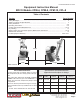
E-CPL8-CPM-4-8-10-I-0112 CPM-4-8-10-SACRALITE8 OPERATING INSTRUCTIONS When using Hi-carbon steel or Tungsten Carbide cutter wheels: IMPORTANT! Read the engine manufacturer’s manual, familiarize yourself with engine start procedures. BEFORE STARTING THE ENGINE: *Gasoline models only Be sure that the cutter drum assembly has been properly installed and the cutter drum shaft is in place and secured. Depth Adjustment Crank 1. Select a level place at the job site.
E-CPL8-CPM-4-8-10-I-0112 Before Starting the Machine: • Perform a visual inspection of the entire machine and all daily maintenance according to the Maintenance Schedule on page 15. • Locate and be familiar with all engine/motor and operating controls . • For Gasoline models, obtain the Engine Manufacturer’s Owner’s Manual. Read it and understand it before continuing. Follow the engine manual for break-in instructions. • Use the correct cutters for the job.
E-CPL8-CPM-4-8-10-I-0112 CUTTING Starting the Cut: • Slowly lower the cutter head to the slab surface with the cutter head lever. (Figure 2, Item 1) & (Figure 4) • Lift the knob of the Depth Control to unlock and turn the hand wheel slowly until the cutter head contacts the slab (you will hear the sound of the cutter wheels contacting the slab). Continue adjusting the depth of cut until the desired depth is reached; max depth of cut 3/8” (9.5 mm).
E-CPL8-CPM-4-8-10-I-0112 Cutting Heads / Drums: • Drum assembly revolves at approximately 1200-1800 R. P. M.; Model CPM-10 is a “down-cut” planer, Model CPM-8 is a “down-cut” planer, and ScariLite-8 is a down-cut planer, Model CPM-4 is an “up-cut” planer. Depth of cut is completely determined by the material to be cut, horsepower of the engine/motor and spacing of the cutter wheels on the cutter head.
E-CPL8-CPM-4-8-10-I-0112 CPM-4 DRUM REMOVAL / REPLACEMENT CPM-4 and CPM-8 EDGER ATTACHMENT To remove or replace drum assembly on the CPM-4 remove the two (2) bolts circled securing the drum cover plate in the photo on the left. Next remove the socket head screw as shown in the photo on the left. Slide the drum out as shown in the photo on the left. Reverse procedure to reassemble.
E-CPL8-CPM-4-8-10-I-0112 CPL-8/CPM-8 DRUM REMOVAL / REPLACEMENT RETAINING NUTS (LEFT-HAND THREAD) PLASTIC PLUG DRIVE STUDS DIRECTION OF ROTATION MAIN SHAFT DRUM ASSEMBLY TURN CLOCKWISE TO REMOVE TURN COUNTERCLOCKWISE TO INSTALL. 1. Remove plastic plug from belt guard, set aside for later use. 2. Use a socket wrench to loosen left-hand thread retaining nuts. Be sure the socket is over the outer retaining nut only.
E-CPL8-CPM-4-8-10-I-0112 CPM-10 DRUM REMOVAL / REPLACEMENT To remove or replace the drum assembly on the CPM-10 remove the four (4) bolts circled securing the bearing plate in the photo on the left . NOTE: Bearing grease point. Next remove the bearing plate as shown in the photo on the left. Slide the drum out as shown in the photo on the left. Reverse procedure to reassemble.
E-CPL8-CPM-4-8-10-I-0112 DRY GRINDING Dry Grinding: Dry Grinding creates a large volume of airborne dust. For health reasons, the operator should wear an applicable respirator. The dust may contain chemicals known to cause serious illnesses, including Silicosis a fatal disease of the lungs. Check the chemical properties of the material to be removed and follow all EPA/OSHA regulations.
E-CPL8-CPM-4-8-10-I-0112 What to Expect from your CPM-4, CPM-8, CPM-10, CPL-8 EDCO Concrete Planer The CPM-4-8-10-CPL-8 EDCO concrete Planers were designed to remove material from the surface of concrete slabs. The material may consist of excess concrete, coatings, contaminants such as industrial debris, sealer, paint, production line spill and virtually any foreign substance that creates a safety or health hazard on walks, passageways or floor surfaces.
E-CPL8-CPM-4-8-10-I-0112 Page left blank intentionally 100 Thomas Johnson Drive, Frederick, MD 21702-4600 USA Phone (301) 663-1600 • 1-800-638-3326 Fax (301) 663-1607 • 1-800-447-3326 Website: www.edcoinc.com Email: sales@edcoinc.
E-CPL8-CPM-4-8-10-I-0112 TYPICAL DRUM SET-UPS Surface preparation six shaft drum CPM-4 Surface preparation six shaft drum CPL-8 Surface preparation eight shaft drum CPM-10 Printed in USA 100 Thomas Johnson Drive, Frederick, MD 21702-4600 USA Phone (301) 663-1600 • 1-800-638-3326 ©2012 TVW Fax (301) 663-1607 • 1-800-447-3326 Page 16 Website: www.edcoinc.com Email: sales@edcoinc.
E-CPL8-CPM-4-8-10-I-0112 Remove spark plug lead on gasoline/propane engine models or disconnect the supply voltage connector on electric models before performing any maintenance. Disconnect the power cord at the machine. Maintenance Instructions Refer to the Engine/Motor Manufacturer’s Owner’s Manual for maintenance information specific to the engine/motor used. Never work on or under equipment without first securing the equipment to prevent it from moving or falling.
E-CPL8-CPM-4-8-10-I-0112 CPM-4-8-10-CPL-8 MAINTENANCE INSTRUCTIONS Important! • Check oil level before operation. Change engine oil and filter according to engine manufacturers recommendations. • Clean air filter element daily. Belts: • On new equipment, and after replacing a set of belts, they should be re-tensioned after the first four hours of use. • New belts will be stiff and will loosen with use. Proper belt tension must be maintained to transmit the engine/motor power to the cutting drum.
E-CPL8-CPM-4-8-10-I-0112 Maintenance Schedule Visual Inspection of Entire Machine X Check Engine Oil* X Cutter Shaft Wear (bushings, drum) X Check Cutters for uneven wear X Grease Cutter Assembly Bearings Every Cutter Change As Required Daily Every 4 Hours Before Operation All maintenance to be performed by qualified personnel. Every 40-50 Hours of Operation Read and follow instructions in the engine owner’s manual. Repairs are to be done by authorized EDCO Dealers only.
E-CPL8-CPM-4-8-10-I-0112 LIMITED EQUIPMENT WARRANTY OF SALE - TERMS & CONDITIONS Equipment Development Company, Inc.