
Product Manual


SE-1200 Series Electrocardiograph User Manual Operation Preparations
- 40 -
4.5 Attaching Electrodes to the Patient
4.5.1 Lead Placement
4.5.1.1 Standard 12-Lead Placement
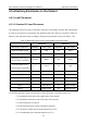
The identifiers and color codes of electrode connectors used comply with IEC/EN requirements.
In order to avoid incorrect connection, the identifiers and color codes are specified in Table 4-1.
Moreover the equivalent codes according to European requirements are given in Table 4-1 too.
Table 4-1 Electrode Connectors and Their Identifiers and Color Codes
European American
Electrode Connectors
Identifier Color Code Identifier Color Code
Right arm/Right deltoid
R
Red RA White
Left arm/Left deltoid
L
Yellow LA Black
Right leg/Upper leg as
close to torso as possible
N or RF Black RL Green
Left leg/Upper leg as
close to torso as possible
F Green LL Red
Chest 1
C1
White/Red V1 Brown/Red
Chest 2
C2
White/Yellow V2 Brown/Yellow
Chest 3
C3
White/Green V3 Brown/Green
Chest 4
C4
White/Brown V4 Brown/Blue
Chest 5
C5
White/Black V5 Brown/Orange
Chest 6
C6
White/Violet V6 Brown/Violet
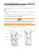
As the following figure shows, the positions of chest electrodes on the body surface are
C1: Fourth intercostal space at the right border of the sternum
C2: Fourth intercostal space at the left border of the sternum
C3: Fifth rib between C2 and C4
C4: Fifth intercostal space on the left midclavicular line
C5: Left anterior axillary line at the horizontal level of C4
C6: Left midaxillary line at the horizontal level of C4