
Product Manual


SE-1200 Series Electrocardiograph User Manual Introduction
- 16 -
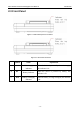
Name Explanation
A Patient Cable Socket Connecting to the patient cable
B Serial Port 1 Connecting to a PC
C USB Socket 1 (Optional) Standard USB socket, connecting to a PC
D
USB Socket 2 (Optional)
Standard USB socket, connecting to a U disk, a
bar code reader or a USB printer recommended
by the manufacturer
E External Input / Output Socket Connecting to the external signal device
F Serial Port 2 Reserved
G Net port Standard net port, connecting to a PC
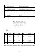
1) Patient Cable Socket
: Applied part of type CF with defibrillator proof
: Caution
Definitions of corresponding pins:
Pin Signal Pin Signal Pin Signal
1
C2 / V2
6
SH
11
F / LL
2
C3 / V3
7
NC
12
C1 / V1
or
NC
3
C4 / V4
8
NC
13
C1 / V1
4
C5 / V5
9
R / RA
14
RF (N) /RL
or NC
5
C6 / V6
10
L / LA
15
RF (N) / RL
NOTE: The left side of “/” is European standard, and the right side is American standard.