
User Manual

Red
pine Signals, Inc. Proprietary and confidential Page 21
RS9110
-
N
-
11
-
02
802.11bgn
WLAN
Module
Data Sheet
Version
1.48
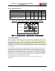
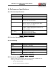
4.4.1.2: Hi
gh Speed Mode
Parameter Symbol
Min. Typ. Max. Units
SDIO_CLK T
s
dio 25 - 50 MHz
SDIO_DATA, input setup time Ts 5 - - ns
SDIO_DATA, input hold time Th 2 - - ns
SDIO_DATA, clock to output
d
el
ay
Tod 5.5 - 12.5 ns
T
a
ble
5: AC Characteristics – SDIO Interface High-Speed Mode
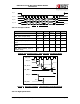
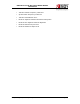
SDIO_CLK
SDIO_DATA
SDIO_DATA
Tod
Th
Ts
Fi
gure
7: Interface Timings – SDIO Interface High-speed Mode
4.
4.2: SPI Interface
The SPI Interface is a full duplex serial host interface, which supports 8-bit and 32-
bit data granularity. It also supports gated mode of SPI clock and both the low and
the high frequency modes. Incase of low frequency host, the data is driven on the
falling edge and sampled on the rising edge and hence, it should be ensured that a
valid data is present on the bus at the immediate rising edge after the SPI chip select
is driven low. For high frequency transmission the data is driven as well as sampled
on rising edge.
This interface has the interrupt pin along with the regular signals clock, chip select,
data in and data out. Device interrupts the host processor regarding the packet
pending event through this interrupt pin. This is an active high signal, and this will
get cleared only after clearing the source of the interrupt, i.e. reading the pending
packet from device. This will be generally connected to a GPIO pin of host platform
and GPIO has to be configured for detecting interrupt on level high, and interrupt
from this GPIO has to be mapped to driver ISR.
The SPI Slave supports mode 0 (SPI_POL=0, SPI_PHA=0) and mode 3 (SPI_POL=1,
SPI_PHA=1).