
User Manual

Red
pine Signals, Inc. Proprietary and confidential Page 18
RS91
10
-
N
-
11
-
02
802.11bgn
WLAN
Module
Data Sheet
Version
1.48
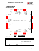
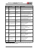
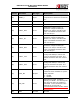
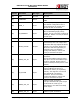
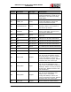
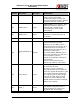
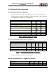
Pin No. Pin Name Pin Type Description
56)
G
ND Ground Ground
57)
R
F_OUT Rfin/Rfout Antenna Port-50 ohms Impedance
58)
G
ND Ground Ground
N
o
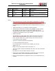
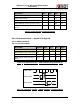
tes:
• Some interfaces are not used in the default configuration or mode of
operation. These include the I2C, GPIO, and UART interfaces. These may
be used in custom applications with appropriate firmware. These are all
fundamentally Inout signals and may be configured either as input or
output.
• JTAG functionality is not included in default firmware.
• The Bluetooth coexistence interface (BT_PRIORITY, WLAN_ACTIVE,
BT_ACTIVE) are also general purpose I/O signals and may be
reprogrammed to be inputs or outputs as needed. Please refer to BT
coexistence application note for more details.
• Sleep clock input:
This should be a 32 kHz clock and is used in power-save modes, if
chosen. During the low power sleep state, the module's wake-up
timer uses the sleep clock - which can have one of three sources
i) an internal 32 kHz oscillator
This is the recommended mode of operation.
ii) a 32 kHz clock fed into this pin,
iii) a 32 kHz crystal connected to pins SLEEP_CLK_X2 and
SLEEP_CLK_X1.
NOTE: The recommended mode of operation is i).
This is a firmware configured GPIO pin and where not used, should be
left open.
By default, an internal 32KHz oscillator is used.
• Please refer to the Module Integration Guide document for reference
schematics and the list of recommended part numbers.
• Please contact Redpine for application notes or for customization of a
solution.