
User Manual

Red
pine Signals, Inc. Proprietary and confidential Page 17
RS9110
-
N
-
11
-
02
802.11bgn
WLAN
Module
Data Sheet
Version
1.48
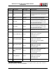
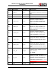
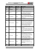
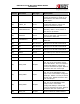
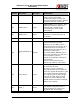
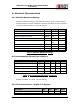
Pin No. Pin Name Pin Type Description
pin, this is the SPI Master clock
o
u
tput. This is a firmware
configured GPIO pin. Where not
used, it should be left open. Default
firmware does not use this pin.
50)
M
ODE_SEL_0 Input
BOOT MODE: On no-connect, boot
parameters will be loaded from
internal flash. Should be left
unconnected so as to enable
bootloading.
51) M
ODE_SEL_1 Input
SDIO MODE: No connect.
SPI Mode: Connect pull down of
4.7Kohms.
52) V
RF28 Power 2.8 Volts LDO O/P
53)
HO
ST_WAKEUP_IN
T
Output
This pin is a GPIO. If this is not
used, it should be left open.
This pin is to be used by those
hosts which enter into power save
mode and which are not able to
detect the regular interrupt pin in
that power save mode.
If used as HOST_WAKEUP_INT, a
pull-up or pull-down of 100K has to
be connected on this pin
based on the polarity indicated to
the firmware.
Active low requires a pull-up.
Active high requires a pull-down.
54) X
TAL_EN_IP Input
This is a GPIO signal by default and
it should be left open.
If used, it can be configured
through firmware to be combined,
through a logical OR operation, with
the internal oscillator enable and
the output given on XTAL_EN pin.
This can be used when a crystal
oscillator is shared between the
WLAN module and other functional
blocks in the system.
55) G
PIO_1 Inout
General purpose input/output. In
the default configuration this is
programmed as an output and
should be left unconnected.