
User Manual

Red
pine Signals, Inc. Proprietary and confidential Page 15
RS9110
-
N
-
11
-
02
802.11bgn
WLAN
Module
Data Sheet
Version
1.48
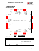
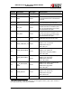
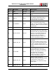
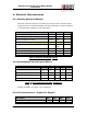
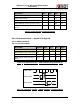
Pin No. Pin Name Pin Type Description
26)
G
ND Ground Ground
27)
V
INBCKDC Power
3.3 Volts input to the
PMU
28)
G
PIO_0 Inout
General purpose input/output. In
the default configuration this is
programmed as an output and
should be left unconnected.
29) B
T_PRIORITY Input
Indicates through ‘logic high’ that
BT is transmitting high priority
traffic. This is a firmware configured
GPIO pin. Where not used, it should
be left open.
30) G
ND Ground Ground
31) W
LAN_ACTIVE Output
When configured for BT
coexistence, this is an output and
indicates with logic high that WLAN
activity is in progress. When low,
BT device has the opportunity to
transmit. This is a firmware
configured GPIO pin. Where not
used, it should be left open.
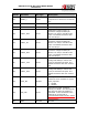
32) S
LEEP_CLK_IN Input
Sleep clock input is NC for default
firmware.
An external 32KHz signal is fed to
this pin if the external 32KHz input
mode is selected. Please refer to
notes on Sleep Clock Input for more
details.
33) B
T_ACTIVE Input
This signal may be used by an
external Bluetooth device to
indicate its activity or impending
activity. This signal is not used in
the default BT coexistence
firmware. This is a firmware
configured GPIO pin. Where not
used, it should be left open.
34) S
LEEP_CLK_X2 Input
32KHz crystal connection
The pin should be left open except
as describe in mode (iii) as
described in note below for Sleep
Clock Input.
35) S
LEEP_CLK_X1 Input 32KHz crystal connection