
Data Sheet
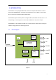
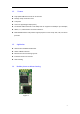
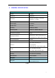
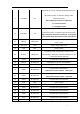
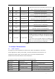
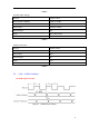
Table Of Contents

9
Alternative Function: BT Power Mode, low level in run
mode, it will be set to high level when fall asleep.
28 PIO5 Bi-directional Programmable input/output line
29 PIO6 Bi-directional
Programmable input/output line
Alternative Function: I
2
C Serial Clock input/output
30 PIO7 Bi-directional
Programmable input/output line
Alternative Function:I
2
C Serial Data input/output
31 PIO8 Bi-directional Programmable input/output line
32 PIO9 Bi-directional
Programmable input/output line
Alternative Function: LED(Default)
33 PIO10 Bi-directional
Programmable input/output line
Alternative Function: BT Status(Default)
34 PIO11 Bi-directional Programmable input/output line
35 GND VSS Power Ground
36 EXT_ANT
RF signal output
By default, this PIN is an empty feet. This PIN can connect
to an external antenna to improve the Bluetooth signal
coverage.
If you need to use an external antenna, by modifying the
module on the 0R resistance to block out the on-board
antenna; Or contact Feasycom for modification.
Table 2
5. Interface Characteristics
5.1 UART Interface
Four signals are used to implement the UART function. When FSC-BT816S is connected to
another digital device, UART_RX and UART_TX transfer data between the two devices. The
remaining two signals, UART_CTS and UART_RTS, can be used to implement RS232
hardware flow control where both are active low indicators.
The interface consists of four-line connection as described in below:
Signal name Driving source Description
UART-TX FSC-BT816S module Data from FSC-BT816S module
UART-RX Host Data from Host
UART-RTS FSC-BT816S module Request to send output of FSC-BT816S module
UART-CTS Host Clear to send input of FSC-BT816S module