
Data Sheet
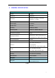
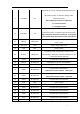
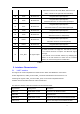
Table Of Contents

8
9 Tran/AIO0 I/O
Alternative Function 1: Analogue programmable I/O line.
Alternative Function 2: Host MCU change UART
transmission mode.
When bluetooth connection established,
H = instruction mode
L = throughput mode
10 Disc/AIO1 I/O
Alternative Function 1: Analogue programmable I/O line.
Alternative Function 2: Host MCU disconnect bluetooth.
When bluetooth connection established, a rising edge
of the PIN will cause disconnection with remote device.
11 RESET CMOS input
Reset if low. Input debounced so must be low for >5ms to
cause a reset.
12 VDD_3V3 VDD Power supply voltage 3.3V
13 GND VSS Power Ground
14 BOOT0 CMOS input
The default is low. (internal 10K resistance drop)
When writing to MCU when using the serial port, this pin
is connected with the high level.
15 PIO15 Bi-directional Programmable input/output line
16
SWCLK Bi-directional Debugging through the clk line(Default)
17
SWDIO Bi-directional Debugging through the data line(Default)
18 PIO12 Bi-directional
Programmable input/output line
Alternative Function: UART3 data output
19 PIO13 Bi-directional
Programmable input/output line
Alternative Function: UART3 data input
20 PIO14 Bi-directional Programmable input/output line
21 GND VSS Power Ground
22 GND VSS Power Ground
23 PIO0 Bi-directional Programmable input/output line
24 PIO1 Bi-directional Programmable input/output line
25 PIO2 Bi-directional Programmable input/output line
26 PIO3 Bi-directional Programmable input/output line
27 PIO4 Bi-directional Programmable input/output line