
Data Sheet
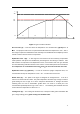
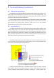
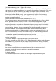
Table Of Contents

13
210
217
℃
250
A
B C D
1 2
0
25
3 4 5 6
min
E
Figure 6: Typical Lead-free Re-flow
Pre-heat zone (A) — This zone raises the temperature at a controlled rate, typically 0.5 – 2
°C/s. The purpose of this zone is to preheat the PCB board and components to 120 ~ 150 °C.
This stage is required to distribute the heat uniformly to the PCB board and completely remove
solvent to reduce the heat shock to components.
Equilibrium Zone 1 (B) — In this stage the flux becomes soft and uniformly encapsulates
solder particles and spread over PCB board, preventing them from being re-oxidized. Also
with elevation of temperature and liquefaction of flux, each activator and rosin get activated
and start eliminating oxide film formed on the surface of each solder particle and PCB board.
The temperature is recommended to be 150° to 210° for 60 to 120 second for this zone.
Equilibrium Zone 2 (C) (optional) — In order to resolve the upright component issue, it is
recommended to keep the temperature in 210 – 217 ° for about 20 to 30 second.
Reflow Zone (D) — The profile in the figure is designed for Sn/Ag3.0/Cu0.5. It can be a
reference for other lead-free solder. The peak temperature should be high enough to achieve
good wetting but not so high as to cause component discoloration or damage. Excessive
soldering time can lead to intermetallic growth which can result in a brittle joint. The
recommended peak temperature (Tp) is 230 ~ 250 °C. The soldering time should be 30 to 90
second when the temperature is above 217 °C.
Cooling Zone (E) — The cooling ate should be fast, to keep the solder grains small which will
give a longer-lasting joint. Typical cooling rate should be 4 °C.