
Data Sheet
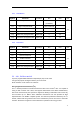
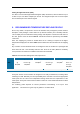
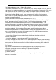
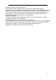
Table Of Contents

11
5.2.1 PCM Master
Symbol Parameter Condition Min Max Unit
Tclk Cycle time 244.14
(4.296MHZ)
15625(64kHZ)
ns
Tw High or low pulse width 50% of Tclk min
Tis PCM-IN setup time 25
Tih PCM-IN hold time 0
Top PCM-OUT propagation time 40pF load 0 10
Top PCM-SYNC propagation time 40pF load 0 10
Table 6
5.2.2 PCM Slave
Symbol Parameter Condition Min Max Unit
Tclk Cycle time 62.67(15MHZ)
ns
Tw High or low pulse width 40% of Tclk
Tis PCM-IN setup time 8
Tih PCM-IN hold time 0
tis PCM-SYNC setup time 8
tih PCM-SYNC hold time 0
Top PCM-OUT propagation time 40pF load 0 21
Table 7
5.3 AIO , PIO lines and I
2
C
Up to 19 programmable bidirectional input/output (I/O) can be used.
Two general purpose analogue interface pin can be used.
PIO6 and PIO7 can be used as I
2
C interface.
Inter-Integrated Circuit Interface (I
2
C)
The I
2
C module provides an interface between the MCU and a serial I
2
C-bus. It is capable of
acting as both a master and a slave, and supports multi-master buses. Both standard-mode,
fast-mode and fast-mode plus speeds are supported, allowing transmission rates all the way
from 10 kbit/s up to 1 Mbit/s. Slave arbitration and timeouts are also provided to allow
implementation of an SMBus compliant system. The interface provided to software by the I
2
C
module, allows both fine-grained control of the transmission process and close to automatic
transfers. Automatic recognition of slave addresses is provided in all energy modes.