
User's Manual
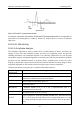
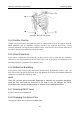
Table Of Contents
- Statement
- Responsibility of the Manufacturer
- Terms Used in this Manual
- Chapter 1 Intended Use and Safety Guidance
- Chapter 2 Overview
- Chapter 3 Installation of Telemetry Monitoring System
- Chapter 4 Basic Operations
- Chapter 5 Patient Management
- Chapter 6 Patient Sector
- Chapter 7 Viewing Single Bed
- Chapter 8 Setting Telemetry Transmitters via MFM-CMS
- Chapter 9 Review
- Chapter 10 System Setup
- Chapter 11 Alarm Management
- Chapter 12 Alarm Information
- Chapter 13 Printing
- Chapter 14 Database Management
- Chapter 15 Monitoring ECG
- 15.1 Overview
- 15.2 ECG Safety Information
- 15.3 ECG Display
- 15.4 Selecting Calculation Lead
- 15.5 Changing Size of ECG Waveform
- 15.6 Changing ECG Filter Settings
- 15.7 ECG Alarm Settings
- 15.8 Monitoring Procedure
- 15.9 Installing Electrodes
- 15.10 Setting Alarm Source
- 15.11 Smart Lead Off
- 15.12 Setting Pace Status
- 15.13 ECG Calibration
- 15.14 ECG Waveform Settings
- 15.15 ST Segment Monitoring
- 15.16 Arr. Monitoring
- Chapter 16 Monitoring RESP
- Chapter 17 Monitoring SpO2
- Chapter 18 Monitoring PR
- Chapter 19 Using Battery
- Chapter 20 Safety
- Chapter 21 Care and Cleaning
- Chapter 22 Maintenance
- Chapter 23 Warranty and Service
- Chapter 24 Accessories
- A Product Specifications
- B EMC Information
- C Default Settings
- D Abbreviation

Telemetry Transmitter User Manual Monitoring SpO
2
5 The device is calibrated to display functional oxygen saturation.
6 The materials with which the patient or any other person can come into contact
conform with the standard of EN ISO 10993-1: 2009.
7 SpO
2
waveform is not proportional to the pulse volume.
8 When the SpO
2
value is potentially incorrect, it will display “?”.
17.3 Measuring SpO
2
1. Select the correct Type in the patient management window (Adult/ Pediat) and click Update
Monitor to confirm, as this is used to optimize the calculation of the SpO2 and pulse
numerics.
2. During measurement, ensure that the application site:
– has a pulsatile flow, ideally with a good circulation perfusion.
– has not changed in its thickness, causing an improper fit of the sensor.
17.4 Measurement Procedure
1. Switch on telemetry monitoring system.
2. Attach the sensor to the appropriate site of the patient finger.
3. Plug the connector of the sensor extension cable into the SpO
2
socket on telemetry
transmitter.
Mounting of the Sensor
WARNING
Inspect the application site every two to three hours to ensure skin quality and correct
optical alignment. If the skin quality changes, move the sensor to another site. Change
the application site at least every four hours.
NOTE:
Injected dyes such as methylene blue or intravascular dyshemoglobins such as
methemoglobin and carboxyhemoglobin may lead to inaccurate measurements.
Interference can be caused by:
High levels of ambient light or strobe lights or flashing lights (such as fire alarm lamps).
- 88 -