
User's Manual
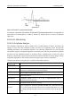
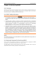
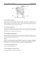
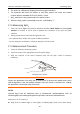
Table Of Contents
- Statement
- Responsibility of the Manufacturer
- Terms Used in this Manual
- Chapter 1 Intended Use and Safety Guidance
- Chapter 2 Overview
- Chapter 3 Installation of Telemetry Monitoring System
- Chapter 4 Basic Operations
- Chapter 5 Patient Management
- Chapter 6 Patient Sector
- Chapter 7 Viewing Single Bed
- Chapter 8 Setting Telemetry Transmitters via MFM-CMS
- Chapter 9 Review
- Chapter 10 System Setup
- Chapter 11 Alarm Management
- Chapter 12 Alarm Information
- Chapter 13 Printing
- Chapter 14 Database Management
- Chapter 15 Monitoring ECG
- 15.1 Overview
- 15.2 ECG Safety Information
- 15.3 ECG Display
- 15.4 Selecting Calculation Lead
- 15.5 Changing Size of ECG Waveform
- 15.6 Changing ECG Filter Settings
- 15.7 ECG Alarm Settings
- 15.8 Monitoring Procedure
- 15.9 Installing Electrodes
- 15.10 Setting Alarm Source
- 15.11 Smart Lead Off
- 15.12 Setting Pace Status
- 15.13 ECG Calibration
- 15.14 ECG Waveform Settings
- 15.15 ST Segment Monitoring
- 15.16 Arr. Monitoring
- Chapter 16 Monitoring RESP
- Chapter 17 Monitoring SpO2
- Chapter 18 Monitoring PR
- Chapter 19 Using Battery
- Chapter 20 Safety
- Chapter 21 Care and Cleaning
- Chapter 22 Maintenance
- Chapter 23 Warranty and Service
- Chapter 24 Accessories
- A Product Specifications
- B EMC Information
- C Default Settings
- D Abbreviation

Telemetry Transmitter User Manual Monitoring RESP
Chapter 16 Monitoring RESP
16.1 Overview
Telemetry transmitter measures respiration from the amount of thoracic impedance between two
ECG electrodes. The change of impedance between the two electrodes, (due to the thoracic
movement), produces a respiratory waveform on the screen.
16.2 RESP Safety Information
WARNING
1 The respiration measurement does not recognize obstructive and mixed apneas - it
only indicates an alarm when a pre-adjusted time has elapsed since the last detected
breath.
2 If operating under conditions according to the EMC Standard EN 60601-1-2 (Radiated
Immunity 3V/m), field strengths above 1V/m may cause erroneous measurements at
various frequencies. Therefore it is recommended to avoid the use of electrically
radiating equipment in close proximity to the respiration measurement unit.
3 Cardiogenic artifact in impedance respiration monitoring may make it difficult to detect
breaths or may otherwise be counted as breaths. In some instances, the breath rate
may also correspond to the heart rate making it difficult to determine if the signal is
due to breathing or the cardiac cycle. Do not rely on RESP monitoring as the sole
method for detecting cessation of breathing. Follow hospital guidelines and best
clinical practices for apnea detection including monitoring additional parameters that
indicate the patient’s oxygenation status, such as EtCO
2
and SpO
2
.
NOTE:
The RESP monitoring is not recommended to be used on patients who are very active, as
this can cause false alarms.
16.3 Electrode Placement for Monitoring RESP
Correct patient skin preparation techniques for electrode placement are important for RESP
measurement: you will find this information in the chapter on ECG.
The RESP signal is always measured between two of the ECG electrodes. There is only one
standard ECG lead for telemetry transmitter: II lead (RA and LL).
- 84 -