
User's Manual
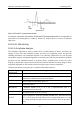
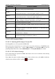
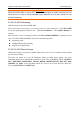
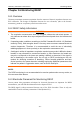
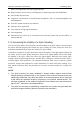
Table Of Contents
- Statement
- Responsibility of the Manufacturer
- Terms Used in this Manual
- Chapter 1 Intended Use and Safety Guidance
- Chapter 2 Overview
- Chapter 3 Installation of Telemetry Monitoring System
- Chapter 4 Basic Operations
- Chapter 5 Patient Management
- Chapter 6 Patient Sector
- Chapter 7 Viewing Single Bed
- Chapter 8 Setting Telemetry Transmitters via MFM-CMS
- Chapter 9 Review
- Chapter 10 System Setup
- Chapter 11 Alarm Management
- Chapter 12 Alarm Information
- Chapter 13 Printing
- Chapter 14 Database Management
- Chapter 15 Monitoring ECG
- 15.1 Overview
- 15.2 ECG Safety Information
- 15.3 ECG Display
- 15.4 Selecting Calculation Lead
- 15.5 Changing Size of ECG Waveform
- 15.6 Changing ECG Filter Settings
- 15.7 ECG Alarm Settings
- 15.8 Monitoring Procedure
- 15.9 Installing Electrodes
- 15.10 Setting Alarm Source
- 15.11 Smart Lead Off
- 15.12 Setting Pace Status
- 15.13 ECG Calibration
- 15.14 ECG Waveform Settings
- 15.15 ST Segment Monitoring
- 15.16 Arr. Monitoring
- Chapter 16 Monitoring RESP
- Chapter 17 Monitoring SpO2
- Chapter 18 Monitoring PR
- Chapter 19 Using Battery
- Chapter 20 Safety
- Chapter 21 Care and Cleaning
- Chapter 22 Maintenance
- Chapter 23 Warranty and Service
- Chapter 24 Accessories
- A Product Specifications
- B EMC Information
- C Default Settings
- D Abbreviation

Telemetry Transmitter User Manual Monitoring ECG
15.15 ST Segment Monitoring
Telemetry transmitter performs ST segment analysis on normal and atrially paced beats and
calculates ST segment elevations and depressions. This information can be displayed in the form
of ST numerics on telemetry transmitter and MFM-CMS(refer to 15.15.2 ST Display).
ST segment monitoring function is shut off by default. You can switch it to On when necessary.
NOTE:
1 ST-segment analysis is intended for use with adult patients only and is not clinically
validated for use with pediatric patients.
2 The ST algorithm has been tested for accuracy of the ST segment data. The
significance of the ST segment changes need to be determined by a clinician.
15.15.1 Open/ Close ST Analysis
Setting ST analysis is operated on MFM-CMS.
To set ST, enter the Parameter Setup Window (way to entering refers to 8.2 Setting Parameters) > Click
ECG on the left physiological parameter list > Choose ON or OFF from ST Analysis, or click
ST on the left physiological parameter list to choose ON or OFF> Click Update Monitor to
confirm.
15.15.2 ST Display
The ST display on telemetry transmitter is as figure 2-4 or figure 2-5.
The ST display on MFM-CMS is on the following areas:
Area 1: ST value area on the right of Single Bed View Sub-Window;
Area 2: parameter value area of patient sector (under the condition that ST should be set as the
active parameter. Detailed operations refer to 6.4.2 Setting Parameters).
15.15.3 ST Alarm Settings
ST alarm settings are operated on MFM-CMS. Please refer to 8.2.1 Parameters Alarm Setting for
more alarm settings.
ST value range is from 2.0 mV to -2.0 mV. The minimum alarm high limit shall be 0.2 mV higher
than the maximum alarm low limit.
15.15.4 About ST Measurement Points
The ST value for each beat complex is the vertical difference between the ISO point and the ST
point, as shown in the diagram below. The isoelectric (ISO) point provides the baseline, and the
ST point is at the midpoint of the ST segment. The J point is where the QRS complex changes its
slope; as it is a fixed distance away from the ST point, it can be useful to help you position the ST
point correctly.
- 80 -