
User's Manual
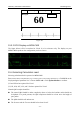
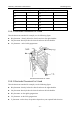
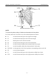
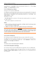
Table Of Contents
- Statement
- Responsibility of the Manufacturer
- Terms Used in this Manual
- Chapter 1 Intended Use and Safety Guidance
- Chapter 2 Overview
- Chapter 3 Installation of Telemetry Monitoring System
- Chapter 4 Basic Operations
- Chapter 5 Patient Management
- Chapter 6 Patient Sector
- Chapter 7 Viewing Single Bed
- Chapter 8 Setting Telemetry Transmitters via MFM-CMS
- Chapter 9 Review
- Chapter 10 System Setup
- Chapter 11 Alarm Management
- Chapter 12 Alarm Information
- Chapter 13 Printing
- Chapter 14 Database Management
- Chapter 15 Monitoring ECG
- 15.1 Overview
- 15.2 ECG Safety Information
- 15.3 ECG Display
- 15.4 Selecting Calculation Lead
- 15.5 Changing Size of ECG Waveform
- 15.6 Changing ECG Filter Settings
- 15.7 ECG Alarm Settings
- 15.8 Monitoring Procedure
- 15.9 Installing Electrodes
- 15.10 Setting Alarm Source
- 15.11 Smart Lead Off
- 15.12 Setting Pace Status
- 15.13 ECG Calibration
- 15.14 ECG Waveform Settings
- 15.15 ST Segment Monitoring
- 15.16 Arr. Monitoring
- Chapter 16 Monitoring RESP
- Chapter 17 Monitoring SpO2
- Chapter 18 Monitoring PR
- Chapter 19 Using Battery
- Chapter 20 Safety
- Chapter 21 Care and Cleaning
- Chapter 22 Maintenance
- Chapter 23 Warranty and Service
- Chapter 24 Accessories
- A Product Specifications
- B EMC Information
- C Default Settings
- D Abbreviation

Telemetry Transmitter User Manual Monitoring ECG
NOTE:
1 Interference from a non-grounded instrument near the patient and ESU interference
can cause inaccuracy of the waveform.
2 IEC/EN60601-1-2 (protection against radiation is 3v/m) specifies that the electrical
field density exceeding 1v/m may cause measurement error in various frequencies. It
is accordingly suggested that do not use equipment generating electrical radiation
near ECG/RESP monitoring devices.
3 If the pacemaker signals are beyond the claimed range, the heart rate may be
calculated incorrectly.
4 In the default settings of MFM-CMS, the ECG waveforms are the first two waveforms
from top in the waveform area.
5 For measurements in or near the heart we recommend connecting the telemetry
transmitter to the potential equalization system.
6 For protecting environment, the used electrodes must be recycled or disposed of
properly.
15.3 ECG Display
15.3.1 ECG Display on Telemetry Transmitter Screen
The figure below is the interface with ECG opened. It is for reference only. The display on your
telemetry transmitter depends on the configuration you have chosen.
Device Status Indicator: including bed number, network symbol, Wi-Fi signal intensity
symbol, power symbol and PACE icon.
Waveform Display: supports 1 channel at most; If ECG is configured and open, the
calculated lead waveform is displayed by default. The waveforms of different leads can be
switched. If the configuration has SpO
2
without ECG, Pleth waveform will be displayed.
Parameter Value;
Trend Graph ( via pressing shifting key to display in turn)
I, II and III lead are optional for 3-lead.
I, II, III, aVR, aVF, aVL, and V lead are optional for 5-lead.
- 72 -