
User's Manual
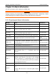
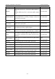
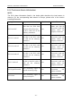
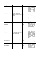
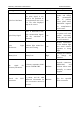
Table Of Contents
- Statement
- Responsibility of the Manufacturer
- Terms Used in this Manual
- Chapter 1 Intended Use and Safety Guidance
- Chapter 2 Overview
- Chapter 3 Installation of Telemetry Monitoring System
- Chapter 4 Basic Operations
- Chapter 5 Patient Management
- Chapter 6 Patient Sector
- Chapter 7 Viewing Single Bed
- Chapter 8 Setting Telemetry Transmitters via MFM-CMS
- Chapter 9 Review
- Chapter 10 System Setup
- Chapter 11 Alarm Management
- Chapter 12 Alarm Information
- Chapter 13 Printing
- Chapter 14 Database Management
- Chapter 15 Monitoring ECG
- 15.1 Overview
- 15.2 ECG Safety Information
- 15.3 ECG Display
- 15.4 Selecting Calculation Lead
- 15.5 Changing Size of ECG Waveform
- 15.6 Changing ECG Filter Settings
- 15.7 ECG Alarm Settings
- 15.8 Monitoring Procedure
- 15.9 Installing Electrodes
- 15.10 Setting Alarm Source
- 15.11 Smart Lead Off
- 15.12 Setting Pace Status
- 15.13 ECG Calibration
- 15.14 ECG Waveform Settings
- 15.15 ST Segment Monitoring
- 15.16 Arr. Monitoring
- Chapter 16 Monitoring RESP
- Chapter 17 Monitoring SpO2
- Chapter 18 Monitoring PR
- Chapter 19 Using Battery
- Chapter 20 Safety
- Chapter 21 Care and Cleaning
- Chapter 22 Maintenance
- Chapter 23 Warranty and Service
- Chapter 24 Accessories
- A Product Specifications
- B EMC Information
- C Default Settings
- D Abbreviation

Telemetry Transmitter User Manual Alarm Information
Chapter 12 Alarm Information
All alarm information will be displayed on MFM-CMS.
WARNING
During monitoring, the physiological alarms including ASYSTOLE, VFIB/VTAC, RESP
APNEA and SpO
2
No Pulse are preset to be on and cannot be turned off.
12.1 Physiological Alarm Information
Message Cause Alarm level
HR High HR measuring value is above the upper alarm limit. User-selectable
HR Low HR measuring value is below the lower alarm limit. User-selectable
ST-X High
ST measuring value is above the upper alarm limit. (X
stands for I, II, III, aVR, aVL, aVF, V)
User-selectable
ST-X Low
ST measuring value is below the lower alarm limit.(X
stands for I, II, III, aVR, aVL, aVF, V)
User-selectable
PVCs High PVCs measuring value is above the upper alarm limit. User-selectable
ASYSTOLE No QRS is detected for 4 consecutive seconds
High
(user-unselectable)
VFIB/VTAC
4 consecutive seconds' fibrillation wave occurs, or
each RR interval for 5 consecutive ventricular beats is
less than 600 ms.
High
(user-unselectable)
VT>2
3 ≤ the number of consecutive PVCs < 5
User-selectable
COUPLET 2 consecutive PVCs User-selectable
BIGEMINY
A dominant rhythm of N, V, N, V (N =
supraventricular beat, V = ventricular
beat) was
detected.
User-selectable
TRIGEMINY A dominant rhythm of N, N, V, N, N,V User-selectable
R ON T
A type of single PVC under the condition that
HR<100,R-
R interval is less than 1/3 the average
interval, followed by a compensating pause of 1.25X
the average R-R interval (the next R wave advances
onto the previous T wave).
User-selectable
PVC Single PVC detected in normal heartbeats. User-selectable
TACHY
Adult: RR interval for 5 consecutive QRS complex
≤
0.5s.
Pediatric: RR interval for 5 consecutive QRS complex
≤ 0.375s.
User-selectable
- 61 -