
User's Manual
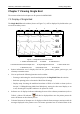
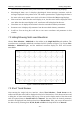
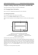
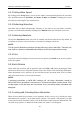
Table Of Contents
- Statement
- Responsibility of the Manufacturer
- Terms Used in this Manual
- Chapter 1 Intended Use and Safety Guidance
- Chapter 2 Overview
- Chapter 3 Installation of Telemetry Monitoring System
- Chapter 4 Basic Operations
- Chapter 5 Patient Management
- Chapter 6 Patient Sector
- Chapter 7 Viewing Single Bed
- Chapter 8 Setting Telemetry Transmitters via MFM-CMS
- Chapter 9 Review
- Chapter 10 System Setup
- Chapter 11 Alarm Management
- Chapter 12 Alarm Information
- Chapter 13 Printing
- Chapter 14 Database Management
- Chapter 15 Monitoring ECG
- 15.1 Overview
- 15.2 ECG Safety Information
- 15.3 ECG Display
- 15.4 Selecting Calculation Lead
- 15.5 Changing Size of ECG Waveform
- 15.6 Changing ECG Filter Settings
- 15.7 ECG Alarm Settings
- 15.8 Monitoring Procedure
- 15.9 Installing Electrodes
- 15.10 Setting Alarm Source
- 15.11 Smart Lead Off
- 15.12 Setting Pace Status
- 15.13 ECG Calibration
- 15.14 ECG Waveform Settings
- 15.15 ST Segment Monitoring
- 15.16 Arr. Monitoring
- Chapter 16 Monitoring RESP
- Chapter 17 Monitoring SpO2
- Chapter 18 Monitoring PR
- Chapter 19 Using Battery
- Chapter 20 Safety
- Chapter 21 Care and Cleaning
- Chapter 22 Maintenance
- Chapter 23 Warranty and Service
- Chapter 24 Accessories
- A Product Specifications
- B EMC Information
- C Default Settings
- D Abbreviation

Telemetry Transmitter User Manual Setting Telemetry Transmitters via MFM-CMS
Chapter 8 Setting Telemetry Transmitters via MFM-CMS
The contents related to this chapter are all operated on MFM-CMS.
8.1 Changing Patient Information
Refer to Section 5.2 Changing Patient Information for more information.
8.2 Setting Parameters
You can open the parameter setup window by two methods:
Method 1: Choose Monitor Parameter Setup in the patient sector.
Method 2: Select the parameter area in the single bed interface, and click on the chosen parameter
area.
1
2
3 4
5
Figure 8-1 The Layout of the Parameter Setup Window
1: Physiological parameter list; 2: Alarm display and configuration list;
3: Physiological parameter attribute and configuration; 4: Update Monitor button;
5: Button for closing the window
The layout of the parameter setup window is shown as Figure 8-1.
The physiological parameter list shows all the available physiological parameter module of the
networked telemetry transmitter. Choose a parameter, the relevant alarm settings and parameter
attribute will be respectively displayed in Area 2 and Area 3. You can configure the alarm settings
(including alarm level, alarm switch, alarm upper and lower limits) and modify parameter
attributes, after which you click Update Monitor to update the relevant settings of the telemetry
transmitter.
Clicking button 5 can close parameter setup window.
- 45 -