
User's Manual
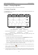
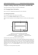
Table Of Contents
- Statement
- Responsibility of the Manufacturer
- Terms Used in this Manual
- Chapter 1 Intended Use and Safety Guidance
- Chapter 2 Overview
- Chapter 3 Installation of Telemetry Monitoring System
- Chapter 4 Basic Operations
- Chapter 5 Patient Management
- Chapter 6 Patient Sector
- Chapter 7 Viewing Single Bed
- Chapter 8 Setting Telemetry Transmitters via MFM-CMS
- Chapter 9 Review
- Chapter 10 System Setup
- Chapter 11 Alarm Management
- Chapter 12 Alarm Information
- Chapter 13 Printing
- Chapter 14 Database Management
- Chapter 15 Monitoring ECG
- 15.1 Overview
- 15.2 ECG Safety Information
- 15.3 ECG Display
- 15.4 Selecting Calculation Lead
- 15.5 Changing Size of ECG Waveform
- 15.6 Changing ECG Filter Settings
- 15.7 ECG Alarm Settings
- 15.8 Monitoring Procedure
- 15.9 Installing Electrodes
- 15.10 Setting Alarm Source
- 15.11 Smart Lead Off
- 15.12 Setting Pace Status
- 15.13 ECG Calibration
- 15.14 ECG Waveform Settings
- 15.15 ST Segment Monitoring
- 15.16 Arr. Monitoring
- Chapter 16 Monitoring RESP
- Chapter 17 Monitoring SpO2
- Chapter 18 Monitoring PR
- Chapter 19 Using Battery
- Chapter 20 Safety
- Chapter 21 Care and Cleaning
- Chapter 22 Maintenance
- Chapter 23 Warranty and Service
- Chapter 24 Accessories
- A Product Specifications
- B EMC Information
- C Default Settings
- D Abbreviation

Telemetry Transmitter User Manual Viewing Single Bed
Chapter 7 Viewing Single Bed
The contents related to this chapter are all operated on MFM-CMS.
7.1 Display of Single Bed
The Single Bed View sub-window (shown as Figure 7-1) will be displayed by default when you
access the auxiliary screen.
xxx
xxx
xxx
xxx
60
99
36
.5
40
xx
xx
xx
xx
xx xx
xx
xx
1
6
8
2
5
xxx
xxx
xxx
xx
xx
xx
xx
xx
xx
xx
xx
4
7
9
xxx
3
xxx
Figure 7-1 Single Bed View Sub-Window
1: Patient information area 2: Toolbar 3: Indicator area
4: Technical alarm area/ Prompts area 5: Physiological alarm area 6: Short trend area
7: Waveform area 8: Parameter area 9: Scroll bar
Patient information area: It displays the bed No., patient name, gender, patient type, and
telemetry transmitter name.
You can perform the following functions via the toolbar:
– Freezing or unfreezing the waveforms displayed in the Single Bed View sub-window.
– Real-time printing (refer to Section 6.6 Real-Time Printing).
– Display setup: choosing the multi-lead waveform of ECG to be hided or shown (refer to
Section 7.2 Hiding/Showing Multi-Lead Waveform); setting the short trend display to on
or off; choosing the OxyCRG window to be opened or closed.
Indicator area: It displays indicators indicating the state of the telemetry transmitters (refer to
Table 6-). Nurse Call indicator will also be displayed here once the patient presses the
nurse call button on the telemetry device.
Technical alarm area/ Prompts area: It displays technical alarm messages consistent with the
messages displayed in the patient sector. The mouse operation here of technical alarm is the
- 42 -