
User's Manual
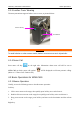
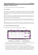
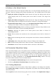
Table Of Contents
- Statement
- Responsibility of the Manufacturer
- Terms Used in this Manual
- Chapter 1 Intended Use and Safety Guidance
- Chapter 2 Overview
- Chapter 3 Installation of Telemetry Monitoring System
- Chapter 4 Basic Operations
- Chapter 5 Patient Management
- Chapter 6 Patient Sector
- Chapter 7 Viewing Single Bed
- Chapter 8 Setting Telemetry Transmitters via MFM-CMS
- Chapter 9 Review
- Chapter 10 System Setup
- Chapter 11 Alarm Management
- Chapter 12 Alarm Information
- Chapter 13 Printing
- Chapter 14 Database Management
- Chapter 15 Monitoring ECG
- 15.1 Overview
- 15.2 ECG Safety Information
- 15.3 ECG Display
- 15.4 Selecting Calculation Lead
- 15.5 Changing Size of ECG Waveform
- 15.6 Changing ECG Filter Settings
- 15.7 ECG Alarm Settings
- 15.8 Monitoring Procedure
- 15.9 Installing Electrodes
- 15.10 Setting Alarm Source
- 15.11 Smart Lead Off
- 15.12 Setting Pace Status
- 15.13 ECG Calibration
- 15.14 ECG Waveform Settings
- 15.15 ST Segment Monitoring
- 15.16 Arr. Monitoring
- Chapter 16 Monitoring RESP
- Chapter 17 Monitoring SpO2
- Chapter 18 Monitoring PR
- Chapter 19 Using Battery
- Chapter 20 Safety
- Chapter 21 Care and Cleaning
- Chapter 22 Maintenance
- Chapter 23 Warranty and Service
- Chapter 24 Accessories
- A Product Specifications
- B EMC Information
- C Default Settings
- D Abbreviation

Telemetry Transmitter User Manual Patient Sector
Chapter 6 Patient Sector
The contents related to this chapter are all operated on MFM-CMS.
6.1 Overview
Refer to Section 2.5.2.2 Patient Sectors for information about the three types of state of the patient
sector. Refer to Section 2.5.4 Large Font Display for information about the large font display
mode in the patient sector. Refer to Section 2.5.2 Main Screen for information about the layout of
patient sectors.
When the patient sector is in the improper offline state or in the networked monitoring state, you
can open a menu by clicking on the patient information area. Refer to Section 6.3 Menu in the
Patient Sector for more information about the menu.
When the patient sector is in the improper offline state or in the networked monitoring state, you
can access the auxiliary screen by clicking on the waveform area or parameter area in the patient
sector.
When the patient sector is in the disconnected state, you can switch between patient sectors by
clicking on the patient sector. Refer to Section 5.3 Switching Patient sector for more information.
6.2 Networked Monitoring Display
The display of patient sector which is networked is shown as Figure 6-1.
xxx
xxx
xxx
xxx
60
99
36.5 40
xx xx
xx xx
xx
xx xx xx
3
1
2
4 5
xxx
xxx
xxx
Figure 6-1 Display of the Networked Patient Sector
1: Waveform area 2: Parameter area 3: Patient information area
4: Technical alarm/ Prompts/ indicator area 5: Physiological alarm area
Waveform area and parameter area: It displays some of real-time monitoring waveforms and
parameter values. Refer to Section 6.4 Parameter / Waveform Setup.
Patient information area: It displays the bed number, device name and patient name.
Technical alarm/ Prompts/ Indicator area: It displays the technical alarm messages when a
technical alarm occurs (refer to Section 11.1.2 Technical Alarms). Click on the technical
alarm message, and the list for the current technical alarms will be displayed. When no
technical alarms and no prompts occur, it displays the indicators (shown as Table 6-)
- 37 -