
User's Manual
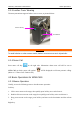
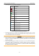
Table Of Contents
- Statement
- Responsibility of the Manufacturer
- Terms Used in this Manual
- Chapter 1 Intended Use and Safety Guidance
- Chapter 2 Overview
- Chapter 3 Installation of Telemetry Monitoring System
- Chapter 4 Basic Operations
- Chapter 5 Patient Management
- Chapter 6 Patient Sector
- Chapter 7 Viewing Single Bed
- Chapter 8 Setting Telemetry Transmitters via MFM-CMS
- Chapter 9 Review
- Chapter 10 System Setup
- Chapter 11 Alarm Management
- Chapter 12 Alarm Information
- Chapter 13 Printing
- Chapter 14 Database Management
- Chapter 15 Monitoring ECG
- 15.1 Overview
- 15.2 ECG Safety Information
- 15.3 ECG Display
- 15.4 Selecting Calculation Lead
- 15.5 Changing Size of ECG Waveform
- 15.6 Changing ECG Filter Settings
- 15.7 ECG Alarm Settings
- 15.8 Monitoring Procedure
- 15.9 Installing Electrodes
- 15.10 Setting Alarm Source
- 15.11 Smart Lead Off
- 15.12 Setting Pace Status
- 15.13 ECG Calibration
- 15.14 ECG Waveform Settings
- 15.15 ST Segment Monitoring
- 15.16 Arr. Monitoring
- Chapter 16 Monitoring RESP
- Chapter 17 Monitoring SpO2
- Chapter 18 Monitoring PR
- Chapter 19 Using Battery
- Chapter 20 Safety
- Chapter 21 Care and Cleaning
- Chapter 22 Maintenance
- Chapter 23 Warranty and Service
- Chapter 24 Accessories
- A Product Specifications
- B EMC Information
- C Default Settings
- D Abbreviation

Telemetry Transmitter User Manual Basic Operations
WARNING
It is prohibited for patient to install or replace battery.
4.1.2 Switching On
Under switch off condition, keep pressing power supply switch at least for 2 seconds to turn on.
Then the green light on power supply switch will occur. At the same time, the following self-tests
will be carried out:
Read parameters configuration. Refer to 2.4 Configuration for configuration information;
Check ECG accessory compatibility.
When accessory is not compatible, the screen will display “Check the ECG accessories”; When
compatible and ECG module is active, telemetry transmitter will check ECG leads connection.
The screen will enter into main interface under condition of correct leads connection. Under leads
off or wrong connection, the screen will display ECG leads connection sketch in which wrong
leads position and correct leads position will be indicated. ECG leads connection sketch will
disappear in these conditions, leads connection restoring normally, pressing shifting key or over
60 seconds.
Read automatically ECG leads type (3-lead or 5-lead) and ECG leads style (AHA or IEC).
NOTE:
During switch on, user should confirm the green light on power supply switch occurs and
screen displays normally. Nurse call and patient call sounds should also be tested
normally. Refer to 5.7 Nurse Call / Patient Call for more nurse call and patient call
information.
4.1.3 Switching Off
Under telemetry transmitter on:
When power is in 0 level or screen is open, keep pressing at least for 3 seconds to turn off..
4.1.4 Open/ Close Screen
Under telemetry transmitter on, when screen is closed with non-0-level of battery, press is to
open screen. The screen will be back to the interface last used after opening again.
Under screen open condition, do one of the following method to close:
1. Press power supply switch;
2. Without any actions in 15 seconds, screen will close automatically.
After closing, monitoring and net connection keep working normally.
- 30 -