
User's Manual
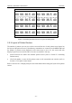

Table Of Contents
- Statement
- Responsibility of the Manufacturer
- Terms Used in this Manual
- Chapter 1 Intended Use and Safety Guidance
- Chapter 2 Overview
- Chapter 3 Installation of Telemetry Monitoring System
- Chapter 4 Basic Operations
- Chapter 5 Patient Management
- Chapter 6 Patient Sector
- Chapter 7 Viewing Single Bed
- Chapter 8 Setting Telemetry Transmitters via MFM-CMS
- Chapter 9 Review
- Chapter 10 System Setup
- Chapter 11 Alarm Management
- Chapter 12 Alarm Information
- Chapter 13 Printing
- Chapter 14 Database Management
- Chapter 15 Monitoring ECG
- 15.1 Overview
- 15.2 ECG Safety Information
- 15.3 ECG Display
- 15.4 Selecting Calculation Lead
- 15.5 Changing Size of ECG Waveform
- 15.6 Changing ECG Filter Settings
- 15.7 ECG Alarm Settings
- 15.8 Monitoring Procedure
- 15.9 Installing Electrodes
- 15.10 Setting Alarm Source
- 15.11 Smart Lead Off
- 15.12 Setting Pace Status
- 15.13 ECG Calibration
- 15.14 ECG Waveform Settings
- 15.15 ST Segment Monitoring
- 15.16 Arr. Monitoring
- Chapter 16 Monitoring RESP
- Chapter 17 Monitoring SpO2
- Chapter 18 Monitoring PR
- Chapter 19 Using Battery
- Chapter 20 Safety
- Chapter 21 Care and Cleaning
- Chapter 22 Maintenance
- Chapter 23 Warranty and Service
- Chapter 24 Accessories
- A Product Specifications
- B EMC Information
- C Default Settings
- D Abbreviation

Telemetry Transmitter User Manual Overview
the volume adjustor to your desired volume.
NOTE:
MFM-
CMS will keep mute as soon as mute check box
is ticked. If a new alarm occurs, the system won’t break
mute status and keep mute until mute check box is
ticked again. Please use it with caution.
Networked State
The networked state window has 64 panes (shown as Figure 2-10) representing the 64 telemetry
transmitters that can be supported and connected to the MFM-CMS. The pane only displays the
telemetry transmitter’s number. You can access the single bed interface by clicking on the pane.
1
2 3
…
…
4
Figure
2-10 Networked State
The pane has the several types of state:
Blank: Network disconnected (refer to Section 2.5.2.2 Patient Sectors).
With grey background and white bed number: Improper offline (refer to Section 2.5.2.2
Patient Sectors).
With green background: Networked monitoring (refer to Section 2.5.2.2 Patient Sectors);
without physiological alarm.
With yellow background: Networked monitoring (refer to Section 2.5.2.2 Patient Sectors);
with medium or low level physiological alarm.
With red background: Networked monitoring (refer to Section 2.5.2.2 Patient Sectors); with
high level physiological alarm.
2.5.3 Auxiliary Screen
If the patient sector is in the state either of improper offline or networked monitoring, you can
access the auxiliary screen by clicking the waveform area or parameter area on the patient sector.
The auxiliary screen on a single display is shown as Figure 2-11, and the one on dual displays is
shown as Figure 2-12.
- 20 -