
User's Manual
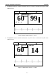
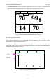
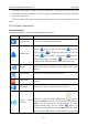
Table Of Contents
- Statement
- Responsibility of the Manufacturer
- Terms Used in this Manual
- Chapter 1 Intended Use and Safety Guidance
- Chapter 2 Overview
- Chapter 3 Installation of Telemetry Monitoring System
- Chapter 4 Basic Operations
- Chapter 5 Patient Management
- Chapter 6 Patient Sector
- Chapter 7 Viewing Single Bed
- Chapter 8 Setting Telemetry Transmitters via MFM-CMS
- Chapter 9 Review
- Chapter 10 System Setup
- Chapter 11 Alarm Management
- Chapter 12 Alarm Information
- Chapter 13 Printing
- Chapter 14 Database Management
- Chapter 15 Monitoring ECG
- 15.1 Overview
- 15.2 ECG Safety Information
- 15.3 ECG Display
- 15.4 Selecting Calculation Lead
- 15.5 Changing Size of ECG Waveform
- 15.6 Changing ECG Filter Settings
- 15.7 ECG Alarm Settings
- 15.8 Monitoring Procedure
- 15.9 Installing Electrodes
- 15.10 Setting Alarm Source
- 15.11 Smart Lead Off
- 15.12 Setting Pace Status
- 15.13 ECG Calibration
- 15.14 ECG Waveform Settings
- 15.15 ST Segment Monitoring
- 15.16 Arr. Monitoring
- Chapter 16 Monitoring RESP
- Chapter 17 Monitoring SpO2
- Chapter 18 Monitoring PR
- Chapter 19 Using Battery
- Chapter 20 Safety
- Chapter 21 Care and Cleaning
- Chapter 22 Maintenance
- Chapter 23 Warranty and Service
- Chapter 24 Accessories
- A Product Specifications
- B EMC Information
- C Default Settings
- D Abbreviation

Telemetry Transmitter User Manual Overview
Figure
2-9 Main Screen on Dual Displays
2.5.2.1 System Information Area
The following information will be displayed in this area:
The hospital and department information.
Alarm sound pause indicator and alarm mute indicator .
When connecting with the telemetry transmitters: nurse call indicator and patient call
indicator .
Alarm information and prompts of the MFM-CMS. If more than one piece of message
occurs, they will be displayed circularly. For MFM-CMS system alarms and prompts, please
refer to Appendix II of MFM-CMS Central Monitoring System User Manual.
The system time.
2.5.2.2 Patient Sectors
A patient is monitored by a telemetry transmitter. This telemetry transmitter will occupy a patient
sector when it is connected to the MFM-CMS; meanwhile, the monitoring data will be displayed
in this patient sector. The MFM-CMS supports 64 telemetry transmitters connected to the system;
therefore, a total of 64 patient sectors are available in the MFM-CMS. The layout of patient
sectors may cause some patient sectors temporarily invisible (refer to 2.5.5 Layout of Patient
Sectors).
The patient sector has three types of state:
Network Disconnected: The black background with the white font Disconnected in a patient
sector indicates no patient is admitted or assigned to this patient sector, or the patient
assigned to this sector has been discharged.
Improper Offline: If the system is connected with telemetry transmitter, patient information,
the name of telemetry transmitter, and the message Telemetry No Signal with yellow
background are displayed in the patient sector and accompany with medium level alarm
sound. Improper Offline indicates the patient in this sector has been admitted but is offline.
- 18 -