
User's Manual
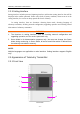
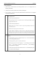
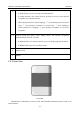
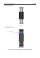
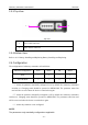
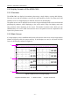
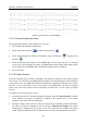
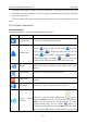
Table Of Contents
- Statement
- Responsibility of the Manufacturer
- Terms Used in this Manual
- Chapter 1 Intended Use and Safety Guidance
- Chapter 2 Overview
- Chapter 3 Installation of Telemetry Monitoring System
- Chapter 4 Basic Operations
- Chapter 5 Patient Management
- Chapter 6 Patient Sector
- Chapter 7 Viewing Single Bed
- Chapter 8 Setting Telemetry Transmitters via MFM-CMS
- Chapter 9 Review
- Chapter 10 System Setup
- Chapter 11 Alarm Management
- Chapter 12 Alarm Information
- Chapter 13 Printing
- Chapter 14 Database Management
- Chapter 15 Monitoring ECG
- 15.1 Overview
- 15.2 ECG Safety Information
- 15.3 ECG Display
- 15.4 Selecting Calculation Lead
- 15.5 Changing Size of ECG Waveform
- 15.6 Changing ECG Filter Settings
- 15.7 ECG Alarm Settings
- 15.8 Monitoring Procedure
- 15.9 Installing Electrodes
- 15.10 Setting Alarm Source
- 15.11 Smart Lead Off
- 15.12 Setting Pace Status
- 15.13 ECG Calibration
- 15.14 ECG Waveform Settings
- 15.15 ST Segment Monitoring
- 15.16 Arr. Monitoring
- Chapter 16 Monitoring RESP
- Chapter 17 Monitoring SpO2
- Chapter 18 Monitoring PR
- Chapter 19 Using Battery
- Chapter 20 Safety
- Chapter 21 Care and Cleaning
- Chapter 22 Maintenance
- Chapter 23 Warranty and Service
- Chapter 24 Accessories
- A Product Specifications
- B EMC Information
- C Default Settings
- D Abbreviation

Telemetry Transmitter User Manual Overview
2.3.5 Top View
Top View
1 ECG cable connector
2 SpO
2
sensor connector
2.3.6 Bottom View
Refer to 4.1.1 Battery Installing and Replacing Battery Installing and Replacing.
2.4 Configuration
The configuration of telemetry transmitter is listed below:
Function Configuration ECG SPO2 PR RESP
ECG
√ × × ○
ECG & SPO2
√ ○ ○ ○
“√” means the parameter standardly configured is on by default after telemetry transmitter
switches on. Changing status should be operated on MFM-CMS. The parameter status last
used will be recovered when the device is switched on again.
“○” means the parameter standardly configured is off by default after telemetry transmitter
switches on. Changing status should be operated on MFM-CMS. The parameter status last used
will be recovered when the device is switched on again.
“×” means the parameter is not configured.
NOTE:
The parameters only standardly configured are applicable.
1
2
- 16 -