
User's Manual
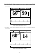
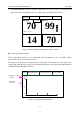
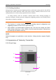
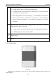
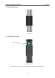
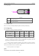
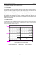
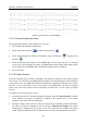
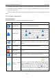
Table Of Contents
- Statement
- Responsibility of the Manufacturer
- Terms Used in this Manual
- Chapter 1 Intended Use and Safety Guidance
- Chapter 2 Overview
- Chapter 3 Installation of Telemetry Monitoring System
- Chapter 4 Basic Operations
- Chapter 5 Patient Management
- Chapter 6 Patient Sector
- Chapter 7 Viewing Single Bed
- Chapter 8 Setting Telemetry Transmitters via MFM-CMS
- Chapter 9 Review
- Chapter 10 System Setup
- Chapter 11 Alarm Management
- Chapter 12 Alarm Information
- Chapter 13 Printing
- Chapter 14 Database Management
- Chapter 15 Monitoring ECG
- 15.1 Overview
- 15.2 ECG Safety Information
- 15.3 ECG Display
- 15.4 Selecting Calculation Lead
- 15.5 Changing Size of ECG Waveform
- 15.6 Changing ECG Filter Settings
- 15.7 ECG Alarm Settings
- 15.8 Monitoring Procedure
- 15.9 Installing Electrodes
- 15.10 Setting Alarm Source
- 15.11 Smart Lead Off
- 15.12 Setting Pace Status
- 15.13 ECG Calibration
- 15.14 ECG Waveform Settings
- 15.15 ST Segment Monitoring
- 15.16 Arr. Monitoring
- Chapter 16 Monitoring RESP
- Chapter 17 Monitoring SpO2
- Chapter 18 Monitoring PR
- Chapter 19 Using Battery
- Chapter 20 Safety
- Chapter 21 Care and Cleaning
- Chapter 22 Maintenance
- Chapter 23 Warranty and Service
- Chapter 24 Accessories
- A Product Specifications
- B EMC Information
- C Default Settings
- D Abbreviation

Telemetry Transmitter User Manual Overview
5. ECG&SpO2&RESP Interface: includes information area, ECG value of calculated lead,
SpO2 value, PR value and RR value. It’s actually the same with default interface.
70
SpO
2
%
99
HR bpm
RR rpm
14
ST
II
0.
10
PR
bpm
70
PACE Icon
Bed No
.
Networking Icon
Battery Status
Wireless signal Icon
Figure 2-6 ECG & SpO2 & PR & RESP Interface(ST ON)
Trend Graph Main Interface
Trend Graph Main Interface can be displayed when parameters are on. It includes current
patient’s data only, not the history patient’s.
According to the parameters customer chosen, trend graph main interface has four kinds: ECG
Trend Graph Main Interface, SpO2 Trend Graph Main Interface, PR Trend Graph Main Interface
and RESP Trend Graph Main Interface.
Networking Icon
Bed No
.
Wireless signal Icon
Battery Status
min
XXX
0
xx
-90 -60 -30
xx
Figure 2-7 Trend Graph Main Interface
Parameter name
and unit
Parameter
scale value
- 11 -