
User's Manual


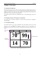
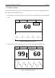
Table Of Contents
- Statement
- Responsibility of the Manufacturer
- Terms Used in this Manual
- Chapter 1 Intended Use and Safety Guidance
- Chapter 2 Overview
- Chapter 3 Installation of Telemetry Monitoring System
- Chapter 4 Basic Operations
- Chapter 5 Patient Management
- Chapter 6 Patient Sector
- Chapter 7 Viewing Single Bed
- Chapter 8 Setting Telemetry Transmitters via MFM-CMS
- Chapter 9 Review
- Chapter 10 System Setup
- Chapter 11 Alarm Management
- Chapter 12 Alarm Information
- Chapter 13 Printing
- Chapter 14 Database Management
- Chapter 15 Monitoring ECG
- 15.1 Overview
- 15.2 ECG Safety Information
- 15.3 ECG Display
- 15.4 Selecting Calculation Lead
- 15.5 Changing Size of ECG Waveform
- 15.6 Changing ECG Filter Settings
- 15.7 ECG Alarm Settings
- 15.8 Monitoring Procedure
- 15.9 Installing Electrodes
- 15.10 Setting Alarm Source
- 15.11 Smart Lead Off
- 15.12 Setting Pace Status
- 15.13 ECG Calibration
- 15.14 ECG Waveform Settings
- 15.15 ST Segment Monitoring
- 15.16 Arr. Monitoring
- Chapter 16 Monitoring RESP
- Chapter 17 Monitoring SpO2
- Chapter 18 Monitoring PR
- Chapter 19 Using Battery
- Chapter 20 Safety
- Chapter 21 Care and Cleaning
- Chapter 22 Maintenance
- Chapter 23 Warranty and Service
- Chapter 24 Accessories
- A Product Specifications
- B EMC Information
- C Default Settings
- D Abbreviation

Telemetry Transmitter User Manual Overview
Chapter 2 Overview
2.1 System Introduction
Telemetry monitoring system can realize an integrated monitoring for multiple mobile patients or
bed patients via wireless network. It is easy for extending and net deploying. Among the system,
telemetry transmitter owns small size, light weight and long battery life and works with
MFM-CMS to form an integrated monitoring solution.
The detailed operation instructions of MFM-CMS refer to Central Monitoring System User
Manual
2.2 Display Screen of Telemetry Transmitter
The display screen of telemetry transmitter is associated with the parameters’ configuration
customer bought.
2.2.1 Default Interface
The default interface has two parts: Information Area and Parameter Value Area. Under
parameters on, the symbol ?will be displayed in parameter value area if measuring is not
implemented or the measured value is invalid. The default interface with three parameters on is as
follow:
70
SpO
2 %
99
HR bpm
RR rpm
14
ST II 0.10
PR bpm
70
PACE Icon
Bed No.
Networking Icon
Battery Status
Wireless signal Icon
Figure 2-1 ECG + SpO2 + RESP Default Interface(ST on)
Information
Area
Parameter
Value Area
Pulse Bar Graph
- 8 -