
User's Manual
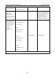
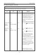
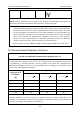
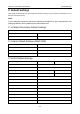

Table Of Contents
- Statement
- Responsibility of the Manufacturer
- Terms Used in this Manual
- Chapter 1 Intended Use and Safety Guidance
- Chapter 2 Overview
- Chapter 3 Installation of Telemetry Monitoring System
- Chapter 4 Basic Operations
- Chapter 5 Patient Management
- Chapter 6 Patient Sector
- Chapter 7 Viewing Single Bed
- Chapter 8 Setting Telemetry Transmitters via MFM-CMS
- Chapter 9 Review
- Chapter 10 System Setup
- Chapter 11 Alarm Management
- Chapter 12 Alarm Information
- Chapter 13 Printing
- Chapter 14 Database Management
- Chapter 15 Monitoring ECG
- 15.1 Overview
- 15.2 ECG Safety Information
- 15.3 ECG Display
- 15.4 Selecting Calculation Lead
- 15.5 Changing Size of ECG Waveform
- 15.6 Changing ECG Filter Settings
- 15.7 ECG Alarm Settings
- 15.8 Monitoring Procedure
- 15.9 Installing Electrodes
- 15.10 Setting Alarm Source
- 15.11 Smart Lead Off
- 15.12 Setting Pace Status
- 15.13 ECG Calibration
- 15.14 ECG Waveform Settings
- 15.15 ST Segment Monitoring
- 15.16 Arr. Monitoring
- Chapter 16 Monitoring RESP
- Chapter 17 Monitoring SpO2
- Chapter 18 Monitoring PR
- Chapter 19 Using Battery
- Chapter 20 Safety
- Chapter 21 Care and Cleaning
- Chapter 22 Maintenance
- Chapter 23 Warranty and Service
- Chapter 24 Accessories
- A Product Specifications
- B EMC Information
- C Default Settings
- D Abbreviation

Telemetry Transmitter User Manual EMC Information
the following symbol:
NOTE 1 At 80 MHz and 800 MHz, the higher frequency range applies.
NOTE 2
These guidelines may not apply in all situations. Electromagnetic propagation is
affected by absorption and reflection from structures, objects and people.
a
Field strengths from fixed transmitters, such as base stations for radio
(cellular/cordless) telephones and land mobile radios, amateur radio, AM and FM radio
broadcast and TV broadcast cannot be predicted theoretically with accuracy. To assess
the electr
omagnetic environment due to fixed RF transmitters, an electromagnetic site
survey should be considered. If the measured field strength in the location in which
iT20 is used exceeds the applicable RF compliance level above, iT20
should be
observed to verify normal operation. If abnormal performance is observed, additional
measures may be necessary, such as reorienting or relocating iT20.
b
Over the frequency range 150kHz to 80MHz, field strengths should be less than 3V/m.
B.4 Recommended Separation Distances
Recommended separation distances between
portable and mobile RF communications equipment and iT20
iT20 is intended for use in an electromagnetic environment in which radiated RF disturbances
are controlled. The customer or the user of iT20 can help prevent electromagnetic interference
by maintaining a minimum distance between portable and mobile RF communications
equipment (transmitters) and iT20
as recommended below, according to the maximum output
power of the communications equipment.
Rated maximum
output power of
transmitter
(W)
Separation distance according to frequency of transmitter(m)
150 kHz to 80 MHz
Pd
2.1
=
80 MHz to 800 MHz
Pd
2.
1=
800 MHz to 2.5 GHz
Pd
3.
2=
0.01
0.12
0.12
0.23
0.1
0.38
0.38
0.73
1
1.2
1.2
2.3
10
3.8
3.8
7.3
100
12
12
23
For transmitters rated at a maximum output power not listed above, the recommended
separation distance d in metres (m) can be estimated using the equation applicable to the
frequency of the transmitter, whe
re P is the maximum output power rating of the transmitter in
watts (W) according to the transmitter manufacturer.
- 120 -