
User's Manual
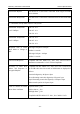
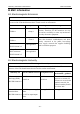
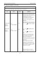
Table Of Contents
- Statement
- Responsibility of the Manufacturer
- Terms Used in this Manual
- Chapter 1 Intended Use and Safety Guidance
- Chapter 2 Overview
- Chapter 3 Installation of Telemetry Monitoring System
- Chapter 4 Basic Operations
- Chapter 5 Patient Management
- Chapter 6 Patient Sector
- Chapter 7 Viewing Single Bed
- Chapter 8 Setting Telemetry Transmitters via MFM-CMS
- Chapter 9 Review
- Chapter 10 System Setup
- Chapter 11 Alarm Management
- Chapter 12 Alarm Information
- Chapter 13 Printing
- Chapter 14 Database Management
- Chapter 15 Monitoring ECG
- 15.1 Overview
- 15.2 ECG Safety Information
- 15.3 ECG Display
- 15.4 Selecting Calculation Lead
- 15.5 Changing Size of ECG Waveform
- 15.6 Changing ECG Filter Settings
- 15.7 ECG Alarm Settings
- 15.8 Monitoring Procedure
- 15.9 Installing Electrodes
- 15.10 Setting Alarm Source
- 15.11 Smart Lead Off
- 15.12 Setting Pace Status
- 15.13 ECG Calibration
- 15.14 ECG Waveform Settings
- 15.15 ST Segment Monitoring
- 15.16 Arr. Monitoring
- Chapter 16 Monitoring RESP
- Chapter 17 Monitoring SpO2
- Chapter 18 Monitoring PR
- Chapter 19 Using Battery
- Chapter 20 Safety
- Chapter 21 Care and Cleaning
- Chapter 22 Maintenance
- Chapter 23 Warranty and Service
- Chapter 24 Accessories
- A Product Specifications
- B EMC Information
- C Default Settings
- D Abbreviation

Telemetry Transmitter User Manual EMC Information
B.3 Electromagnetic Immunity
Electromagnetic immunity
iT20 is intended for use in the electromagnetic environment specified below. The customer or
the user of iT20 should assure that it is used in such an environment.
Immunity
test
IEC/EN 60601 test
level
Compliance
level
Electromagnetic environment -
guidance
Conducted RF
IEC/EN
61000-4-6
Radiated RF
IEC/EN
61000-4-3
3 V
rms
150 kHz to 80 MHz
3 V/m
80 MHz to 2.5 GHz
3 V
rms
3 V/m
Portable and mobile RF
communications equipment should
be used no closer to any part of iT20,
including cables, than the
recommended separation distance
calculated from the equation
applicable to the frequency of the
transmitter.
Recommended separation distance
Pd
2.1
=
150 kHz to 80 MHz
P
d
2.1=
80 MHz to 800
MHz
P
d
3.2
=
800 MHz to 2.5
GHz
Where P is the maximum output
power rating of the transmitter in
watts (W) according to the
transmitter manufacturer and d is the
recommended separation distance in
metres (m).
Field strengths from fixed RF
transmitters, as determined by an
electromagnetic site survey,
a
should
be less than the compliance level in
each frequency range.
b
Interference may occur in the
vicinity of equipment marked with
- 119 -