
User's Manual
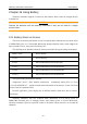

Table Of Contents
- Statement
- Responsibility of the Manufacturer
- Terms Used in this Manual
- Chapter 1 Intended Use and Safety Guidance
- Chapter 2 Overview
- Chapter 3 Installation of Telemetry Monitoring System
- Chapter 4 Basic Operations
- Chapter 5 Patient Management
- Chapter 6 Patient Sector
- Chapter 7 Viewing Single Bed
- Chapter 8 Setting Telemetry Transmitters via MFM-CMS
- Chapter 9 Review
- Chapter 10 System Setup
- Chapter 11 Alarm Management
- Chapter 12 Alarm Information
- Chapter 13 Printing
- Chapter 14 Database Management
- Chapter 15 Monitoring ECG
- 15.1 Overview
- 15.2 ECG Safety Information
- 15.3 ECG Display
- 15.4 Selecting Calculation Lead
- 15.5 Changing Size of ECG Waveform
- 15.6 Changing ECG Filter Settings
- 15.7 ECG Alarm Settings
- 15.8 Monitoring Procedure
- 15.9 Installing Electrodes
- 15.10 Setting Alarm Source
- 15.11 Smart Lead Off
- 15.12 Setting Pace Status
- 15.13 ECG Calibration
- 15.14 ECG Waveform Settings
- 15.15 ST Segment Monitoring
- 15.16 Arr. Monitoring
- Chapter 16 Monitoring RESP
- Chapter 17 Monitoring SpO2
- Chapter 18 Monitoring PR
- Chapter 19 Using Battery
- Chapter 20 Safety
- Chapter 21 Care and Cleaning
- Chapter 22 Maintenance
- Chapter 23 Warranty and Service
- Chapter 24 Accessories
- A Product Specifications
- B EMC Information
- C Default Settings
- D Abbreviation

Telemetry Transmitter User Manual Using Battery
Chapter 19 Using Battery
Telemetry transmitter supports 2 sections of AA batteries which cannot be charged directly
in battery bin.
CAUTION
Remove the batteries from the telemetry transmitter if they are not used for a longer
period of time.
19.1 Battery Status on Screen
The screen of telemetry transmitter as well as technical alarm/ indicator area in patient sector
of MFM-CMS (refer to 6.2 Networked Monitoring Display) displays battery status. Higher the
battery surplus’ level is, more power the battery has.
The following is the definition about the battery level under the typical testing environment.
Battery Level Power Surplus
Level 0 near to using up
Level 1 work continuously no less than 6 mins
Level 2 work continuously no less than 20 hours
Level3 work continuously no less than 40 hours
Level 4 work continuously no less than 60 hours
The typical testing environment includes:
Temperature 25±2℃, SpO
2
module unconnected, continuously testing ECG of 3-lead
(pace off and RESP off), typical network environment with no interference, screen closed and
at least 5 mins of continuous work.
In actual application, power surplus may be different with the table above due to batteries’
performance.
Telemetry transmitter will sent technical alarm information of low battery power to
MFM-CMS informing user of changing battery when battery power is 0-level. Meanwhile,
telemetry transmitter gives out a periodic sound of “du-du-du” whose interval is 10 seconds till
shutdown.
- 92 -