
User's Manual
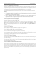
Table Of Contents
- Statement
- Responsibility of the Manufacturer
- Terms Used in this Manual
- Chapter 1 Intended Use and Safety Guidance
- Chapter 2 Overview
- Chapter 3 Installation of Telemetry Monitoring System
- Chapter 4 Basic Operations
- Chapter 5 Patient Management
- Chapter 6 Patient Sector
- Chapter 7 Viewing Single Bed
- Chapter 8 Setting Telemetry Transmitters via MFM-CMS
- Chapter 9 Review
- Chapter 10 System Setup
- Chapter 11 Alarm Management
- Chapter 12 Alarm Information
- Chapter 13 Printing
- Chapter 14 Database Management
- Chapter 15 Monitoring ECG
- 15.1 Overview
- 15.2 ECG Safety Information
- 15.3 ECG Display
- 15.4 Selecting Calculation Lead
- 15.5 Changing Size of ECG Waveform
- 15.6 Changing ECG Filter Settings
- 15.7 ECG Alarm Settings
- 15.8 Monitoring Procedure
- 15.9 Installing Electrodes
- 15.10 Setting Alarm Source
- 15.11 Smart Lead Off
- 15.12 Setting Pace Status
- 15.13 ECG Calibration
- 15.14 ECG Waveform Settings
- 15.15 ST Segment Monitoring
- 15.16 Arr. Monitoring
- Chapter 16 Monitoring RESP
- Chapter 17 Monitoring SpO2
- Chapter 18 Monitoring PR
- Chapter 19 Using Battery
- Chapter 20 Safety
- Chapter 21 Care and Cleaning
- Chapter 22 Maintenance
- Chapter 23 Warranty and Service
- Chapter 24 Accessories
- A Product Specifications
- B EMC Information
- C Default Settings
- D Abbreviation

Telemetry Transmitter User Manual Monitoring SpO
2
(Hint: cover application site with opaque material.)
High-frequency electrical noise, including electro-surgical apparatus and defibrillators
Intravascular dye injections
Significant concentrations of dysfunctional hemoglobin, such as carboxyhemoglobin and
methemoglobin
Excessive patient movement and vibration
Improper sensor application
Low perfusion or high signal attenuation
Venous pulsation
Placement of the sensor on an extremity that has a blood pressure cuff, arterial catheter, or
intravascular line
17.5 Assessing the Validity of a SpO
2
Reading
You can check the quality of the pleth wave and the stability of the SpO
2
values to assess whether
the sensor functions properly and whether the SpO
2
readings are valid. Always use these two
indications simultaneously to assess the validity of a SpO
2
reading.
Generally, the quality of the SpO
2
pleth wave reflects the quality of the light signals obtained by
the sensor. A wave of poor quality manifests a decline of the signal validity. On the other hand,
the stability of the SpO
2
values also reflects the signal quality. Different from varying SpO
2
readings caused by physiological factors, unstable SpO
2
readings are resulted from the sensor’s
receiving signals with interference. The problems mentioned above may be caused by patient
movement, wrong sensor placement or sensor malfunction. To obtain valid SpO
2
readings, try to
limit patient movement, check the placement of the sensor, measure another site or replace the
sensor.
NOTE:
1. The SpO
2
accuracy has been validated in human studies against arterial blood
sample reference measured with a CO-oximeter. Pulse oximeter measurements are
statistically distributed, only about two-thirds of the measurements can be expected
to fall within the specified accuracy compared to CO-oximeter measurements. The
volunteer population in the studies composed of local healthy men and women from
age 19 to 37, with various skin pigmentations.
2. The pulse rate accuracy is obtained by comparison to the pulse rate generated with
an arterial oxygen simulator (also an electronic pulse simulator).
- 89 -