
User's Manual
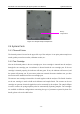
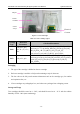
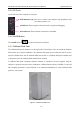
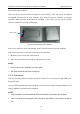
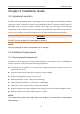
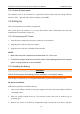
Table Of Contents
- About this Manual
- Statement
- Responsibility of the Manufacturer
- Terms Used in this Manual
- Table of Contents
- Chapter 1 Safety Guide
- Chapter 2 System Overview
- Chapter 3 Installation Guide
- Chapter 4 Setup
- Chapter 5 Patient Analyzing
- Chapter 6 Quality Control (QC) Tests
- Chapter 7 Data Management
- Chapter 8 Online Update
- Chapter 9 Troubleshooting
- Chapter 10 Cleaning, Care and Maintenance
- Chapter 11 Theory
- Chapter 12 Parameters
- Chapter 13 Warranty and Service
- Appendix 1 Specifications
- Appendix 2 Measurement Ranges
- Appendix 3 Reference Ranges
- Appendix 4 EMC Information
- Appendix 5 FCC Information
- Appendix 6 Order List

i15 Blood Gas and Chemistry Analysis System User Manual System Overview
- 16 -
2.4.5 I/O Ports
On the left side of the analyzer are I/O ports:
2.4.6 On/Off Button
The On/Off button is on the left side of the analyzer.
2.4.7 Calibrant Fluid Pack
The calibrant fluid pack chamber is on the right side of the analyzer. You can install the calibrant
fluid pack in it for sensor calibration. The calibrant fluid pack ejector beside the door is used to
open the chamber door. On the calibrant fluid pack ejector is a calibrant fluid pack chamber lock
to help users close the calibrant fluid chamber door securely.
A calibrant fluid pack containing calibrant solutions is intended to be used together with the
analyzer to perform one-point sensor calibration. Calibrant fluid packs are available for 100 and
200 sampling operations. Contact EDAN or its authorized distributors to order calibrant fluid
packs for your system.
Figure 2-3 Calibrant Fluid Pack
USB Interfaces (4): allow you to connect your analyzer with peripherics such
as scanners, printers, etc.
Serial Port: allows engineers from the factory to perform debugging.
Network Port: allows network connection to the DMS.