
User's Manual


PADECG User Manual Preparations Before Operation
- 16 -
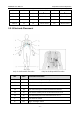
The patient cable includes the main cable and lead wires which can be connected to electrodes.
1. Connect the patient cable to the socket of DX12(iOS) Transmitter.
2. Align all lead wires of the patient cable to avoid twisting, and connect the lead wires to the
electrodes. Firmly attach them.
3.3 Attaching Electrodes
WARNING
Make sure that the conductive parts of electrodes and associated connectors, including
neutral electrodes, do not come in contact with earth or any other conducting objects.
The identifiers and color codes of electrodes used comply with IEC/EN requirements. In order to
avoid incorrect connections, the electrode identifiers and color codes are specified in the
following table. Moreover the equivalent codes according to American requirements are given in
the following table too.
Table 3-1 Electrodes and Their Identifiers and Color Codes
IEC
AHA
WILSON
FRANK
Identifier
Color Code
Identifier
Color Code
Right arm
Right arm
R
Red
RA
White
Left arm
Left arm
L
Yellow
LA
Black
Right leg
Right leg
N or RF
Black
RL
Green
Left leg
Left leg
F
Green
LL
Red
Chest 1
I
C1
White/Red
V1
Brown/Red
Electrode Connector
Lead Wires
Connecting to
DX12(iOS) Transmitter
Main Cable