
User Guide

2 / 14
1. Introduction
Thepurposeof
this
document
is
toprovide
the
usage
of
the
applications
for
transmit and
receive
tests
to
evaluate
the
RF
performance
of
the
RS9113™
(RS9113)
using
a
test
driver in
Linux
e
nvironment.
The
evaluation
board
provides
thenecessaryconnectors
so that
you
can
measure
transmit
and receiveperformance
of
the
PHY,
using
Spectrum
Analyzer
and
SignalGenerator
ineither2.4GHzor
5GHz
(For
RS9113
module).
In
general,
transmit
performance
of
aradio
can
beanalyzedin
threesteps.
Maximum
power:
The
usercan
observe the
RF
output
power
for
a
given maximumgain
supported
bytheRF.
EVM:
Theuser
can
observe
the
EVM
for
a
given
ratedRF
power
as
supported
bytheRF
transceiver.
S
pectralMask:
The
user
can
verify
whether
the
RS9113™
module
meets
the
spectralmask
requirements
definedby
IEEE
standard
for
a
givenmaximumRF
output
power,
in
aparticular
mode
of
operation
like11
a,11b,
11g
etc.
The
receive
performance
of
the
PHY
canbe
analyzedusing
Packet
ErrorRatio
(PER)
test.
TheRx
performance
is
analyzed
by
thesensitivities
atdifferent
data
rates.
In
general,
thesensitivityis
observed
as
10%
Packet
ErrorRatio
(PER)
point
in
11a
and11g,
and
8%
PER
point in
11b.
Thedocument
contains
two
major
sections.
Section
3 describesthe
usage
of
the
‘transmit’
utility,
which
provides
the
options
for
setting
various
parameters
to
carry
out transmit
tests
on
the
RS9113™
device.
Section
4 describesthe
usage
of
the
‘receive’
utility,
whic
h
enables
the
user
to
perform
receive
tests
on
the
RS9113
™
device.
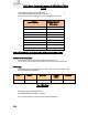
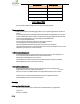
2.
Test
SetupDetails
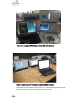
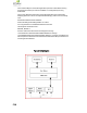
Thediagram
shown
below,illustrates thetest setup
for
evaluatingreceive
and
transmit
performance
of
RS9113™ WLANmodule.
As
shown
in
the
test
setup,the RS9113™
evaluation
board
(EVB)
is plugged
into
Linux
based
laptop either
on
the
SDIO
slot
via
SDIO
connector
or
USB
port
via
USB
cable
through
port J6
on
theEVB.
The
board
is
connected
to
a
WLAN
signal
analyzer
through
amicrowaveco
axialcableto
test
the
Tx
performance.