Preface Copyright This publication, including all photographs, illustrations and software, is protected under international copyright laws, with all rights reserved. Neither this manual, nor any of the material contained herein, may be reproduced without written consent of the author. Version 1.0 Disclaimer The information in this document is subject to change without notice.
ii Declaration of Conformity This device complies with part 15 of the FCC rules. Operation is subject to the following conditions: • This device may not cause harmful interference. • This device must accept any interference received, including interference that may cause undesired operation. Canadian Department of Communications This class B digital apparatus meets all requirements of the Canadian Interferencecausing Equipment Regulations.
iii TABLE OF CONTENTS Preface i Chapter 1 1 Introducing the Motherboard 1 Introduction...................................................................................1 Feature............................................................................................2 Specifications................................................................................4 Motherboard Components..........................................................
iv Security Menu.........................................................................46 Save & Exit Menu...................................................................47 Updating the BIOS..................................................................49 Chapter 4 51 Using the Motherboard Software 51 About the Software DVD-ROM/CD-ROM...................................51 Auto-installing under Windows XP/Vista/7..................................51 Running Setup....................................
1 Chapter 1 Introducing the Motherboard Introduction Thank you for choosing P67H2-A3 motherboard. This motherboard is a high performance, enhanced function motherboard designed to support the LGA1155 socket for 2nd Generation Intel® CoreTM Family & Unlock processors to reach the optimum system performance for high-end business or personal desktop market. This motherboard is based on Intel® P67 Chipset for best desktop platform solution.
2 Feature Processor The motherboard uses an LGA1155 type of socket that carries the following features: • Accommodates 2nd Generation Intel® CoreTM Family & Unlock processors • Supports “Hyper-Threading” technology CPU “Hyper-Threading” technology enables the operating system into thinking it’s hooked up to two processors, allowing two threads to be run in parallel, both on separate “logical” processors within the same physical processor.
3 Expansion Options The motherboard comes with the following expansion options: • • • • Two PCI Express x16 slots for Graphic Interface (the second is x4 bandwidth) One PCI Express x1 slot Two 32-bit PCI v2.2 compliant slots Six 7-pin SATA connectors (2 x SATA 6Gbit/s and 4 x SATA 3Gbit/s) Integrated I/O The motherboard has a full set of I/O ports and connectors: • • • • • • One CLR_COMS button One LAN port Six USB 2.0 ports Two USB 3.
4 Specifications CPU • Chipset • • • LGA1155 socket for 2nd Generation Intel® CoreTM Family & Unlock processors Supports “Hyper-Threading” technology CPU DMI 5.0 GT/S Intel® P67 Chipset Memory • • • Dual-channel DDR3 memory architecture 4 x 240-pin DDR3 DIMM sockets support up to 16 GB Supports DDR3 2133(OC)/1800(OC)/1600/1333/1066 Expansion Slots • • • • Audio • • • 2 x PCI Express Gen2 x16 slots 1 x PCI Express x1 slot 2 x PCI slots Supported by Intel® P67 Chipset - 4 x SATA 3.
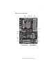
5 Motherboard Components Introducing the Motherboard
6 Table of Motherboard Components LABEL 1. CPU Socket 2. CPU_FAN 3. SYS_FAN 4. DDR3_1~4 5. ATX_POWER 6. SPK 7. SATA1~2 8. SATA3~6 9. F_PANEL 10. F_USB3 11. ME_UNLOCK 12. CASE 13. F_USB2 14. CLR_CMOS 15. F_USB1 16. COM 17. RST_BTN 18. PWR_BTN 19. PWR_FAN 20. SPDIFO 21. F_AUDIO 22. PCI1~2 23. PCIE16X 24. PCIE 25. PCIE16X_T 26. ATX4P 27.
7 Chapter 2 Installing the Motherboard Safety Precautions • • • • • Follow these safety precautions when installing the motherboard Wear a grounding strap attached to a grounded device to avoid damage from static electricity Discharge static electricity by touching the metal case of a safely grounded object before working on the motherboard Leave components in the static-proof bags they came in Hold all circuit boards by the edges.
8 Do not over-tighten the screws as this can stress the motherboard. Checking Jumper Settings This section explains how to set jumpers for correct configuration of the motherboard. Setting Jumpers Use the motherboard jumpers to set system configuration options. Jumpers with more than one pin are numbered. When setting the jumpers, ensure that the jumper caps are placed on the correct pins. The illustrations show a 2-pin jumper. When the jumper cap is placed on both pins, the jumper is SHORT.
9 Checking Jumper Settings The following illustration shows the location of the motherboard jumpers. Pin 1 is labeled. Jumper Settings Jumper Type Description Setting (default) 1-2: NORMAL CLR_CMOS 3-pin Clear CMOS 2-3: CLEAR Before clearing the CMOS, make sure to turn off the system. 1 CLR_CMOS To avoid the system instability after clearing CMOS, we recommend users to enter the main BIOS setting page to “Load Default Settings” and then “Save and Exit Setup”.
10 Installing Hardware Installing the Processor Caution: When installing a CPU heatsink and cooling fan make sure that you DO NOT scratch the motherboard or any of the surface-mount resistors with the clip of the cooling fan. If the clip of the cooling fan scrapes across the motherboard, you may cause serious damage to the motherboard or its components. On most motherboards, there are small surface-mount resistors near the processor socket, which may be damaged if the cooling fan is carelessly installed.
11 CPU Installation Procedure The following illustration shows CPU installation components. A. Opening of the Load Plate · Put your thumb on the tail of the load plate and press the tail down. · Rotate the load plate to fully open position. B. Disengaging of the Load Lever · Hold the hook of lever and pull it to the left side to clear retention tab. · Rotate the load lever to fully open position. C. Removing the Cap · Be careful not to touch the contact at any time. D.
12 1. To achieve better airflow rates and heat dissipation, we suggest that you use a high quality fan with 3800 rpm at least. CPU fan and heatsink installation procedures may vary with the type of CPU fan/ heatsink supplied. The form and size of fan/heatsink may also vary. 2. DO NOT remove the CPU cap from the socket before installing a CPU. 3. Return Material Authorization (RMA) requests will be accepted only if the motherboard comes with the cap on the LGA1155 socket.
13 1. For best performance and compatibility, we recommend that users give priority to the white DIMMs (DDR3_2/DDR3_4 when installing DIMMs. 2. We suggest users not mix memory type. It is recommended to use the same brand and type memory on this motherboard. Do not remove any memory module from its antistatic packaging until you are ready to install it on the motherboard. Handle the modules only by their edges. Do not touch the components or metal parts.
14 Expansion Slots Installing Add-on Cards The slots on this motherboard are designed to hold expansion cards and connect them to the system bus. Expansion slots are a means of adding or enhancing the motherboard’s features and capabilities. With these efficient facilities, you can increase the motherboard’s capabilities by adding hardware that performs tasks that are not part of the basic system.
15 Follow these instructions to install an add-on card: 1 2 3 Remove a blanking plate from the system case corresponding to the slot you are going to use. Install the edge connector of the add-on card into the expansion slot. Ensure that the edge connector is correctly seated in the slot. Secure the metal bracket of the card to the system case with a screw. * For reference only 1.
16 Connecting Optional Devices Refer to the following for information on connecting the motherboard’s optional devices: F_AUDIO: Front Panel Audio header This header allows the user to install auxiliary front-oriented microphone and lineout ports for easier access.
17 SATA3~6: Serial ATAII connectors These connectors are used to support the Serial ATA 3Gb/s devices, simpler disk drive cabling and easier PC assembly. It eliminates limitations of the current Parallel ATA interface. But maintains register compatibility and software compatibility with Parallel ATA. Pin Signal Name 1 3 Ground 5 7 Pin Signal Name TX+ TX- 2 4 RXGround 6 - RX+ - Ground F_USB1~2(USB 2.0): Front Panel USB 2.0 headers The motherboard has three USB 2.0 headers supporting six USB 2.
18 SPDIFO: SPDIF out header This is an optional header that provides an SPDIFO (Sony/Philips Digital Interface) output to digital multimedia device through optical fiber or coaxial connector. Pin 1 2 3 4 Signal Name SPDIFOUT +5V Key GND ME_UNLOCK: ME Unlock Header Pin 1-2 Function Short Unlock Open Lock COM: Onboard serial port header Connect a serial port extension bracket to this header to add a serial port to your system.
19 Installing SATA Hard Drives This section describes how to install SATA devices such as a hard disk drive and a CDROM drive. About SATA Connectors Your motherboard features four SATA 3.0 Gb/s connectors and two SATA 6.0Gb/s connectors supporting a total of six drives SATA refers to Serial ATA (Advanced Technology Attachment) is the standard interface for the SATA hard drives which are currently used in most PCs. These connectors are well designed and will only fit in one orientation.
20 Connecting I/O Devices The backplane of the motherboard has the following I/O ports: PS/2 Keyboard/Mouse Connect the PS/2 Keyboard or PS/2 Mouse to the PS/2 Combo Port combo port. CLR_CMOS Button Use the CLR_CMOS button to clear CMOS. Before clearing CMOS, make sure to turn off the power of the system. LAN Port Connect an RJ-45 jack to the LAN port to connect your computer to the Network. USB 2.0 Ports Use the USB 2.0 ports to connect USB 2.0 devices. USB 3.0 Ports (optional) Use the USB 3.
r 21 Connecting Case Components After you have installed the motherboard into a case, you can begin connecting the motherboard components. Refer to the following: 1 Connect the CPU cooling fan cable to CPU_FAN. 2 Connect the system cooling fan connector to SYS_FAN. 3 Connect the power cooling fan connector to PWR_FAN. 4 Connect the case switches and indicator LEDs to the F_PANEL. 5 Connect the standard power supply connector to ATX_POWER. 6 Connect the connector for graphics interface to ATX4P.
22 2. Connecting 8 power cable Users please note that the 8-pin and 4-pin power cables can both be connected to the ATX12V connector. When installing 8-pin power cable, the latches of power cable and the ATX12V connector match perfectly. 8-pin power cable CPU_FAN: CPU cooling FAN Power Connector Pin 1 2 3 4 Signal Name GND +12V Sense PWM Function System Ground Power +12V Sensor PWM Users please note that the fan connector supports the CPU cooling fan of 1.1A ~ 2.2A (26.4W max) at +12V.
23 PWR_FAN: FAN Power Connector Pin 1 2 3 Signal Name Function System Ground Power +12V Sensor GND +12V Sense SPK: Internal speaker Pin 1 2 3 4 Signal Name VCC Key NC Signal ATX12V: ATX 12V Power Connector Pin Signal Name Pin 1 2 3 4 Ground 5 6 7 8 Ground Ground Ground Signal Name +12V +12V +12V +12V ATX4P: Auxiliary Power Connector for Graphics Interface Pin 1 2 3 4 Signal Name +12V GND GND NC Make sure to connect a 4-pin ATX power cable to ATX4P; otherwise, the system will be unstabl
24 Front Panel Header The front panel header (F_PANEL) provides a standard set of switch and LED headers commonly found on ATX or Micro ATX cases.
25 Chapter 3 Using BIOS About the Setup Utility The computer uses the latest “American Megatrends Inc.” BIOS with support for Windows Plug and Play. The CMOS chip on the motherboard contains the ROM setup instructions for configuring the motherboard BIOS. The BIOS (Basic Input and Output System) Setup Utility displays the system’s configuration status and provides you with options to set system parameters.
26 Press the delete key to access BIOS Setup Utility. Aptio Setup Utility - Copyright (C) 2010 American Megatrends, Inc. Main Advanced Chipset M.I.B III Boot Security System Data System Time Save & Exit Set the Date. Use Tab to switch between Data elements. BIOS Information [ Mon 10/18/2010] [15:22:38] :Select Screen :Select Item Enter : Select +/- : Value F1:General Help F2:Previous Value F3:Optimized Defaults F4:Save & Exit ESC:Exit Version 2.02.1205. Copyright (C) 2010, American Megatrends, Inc.
27 In this manual, default values are enclosed in parenthesis. Submenu items are denoted by a triangle . The default BIOS setting for this motherboard apply for most conditions with optimum performance. We do not suggest users change the default values in the BIOS setup and take no responsibility to any damage caused by changing the BIOS settings.
28 Date & Time The Date and Time items show the current date and time on the computer. If you are running a Windows OS, these items are automatically updated whenever you make changes to the Windows Date and Time Properties utility. Advaned Menu The Advanced menu items allow you to change the settings for the CPU and other system. Main Aptio Setup Utility - Copyright (C) 2010 American Megatrends, Inc. Advanced Chipset M.I.
29 Onboard LAN 1 Controller (Enabled) Use this item to enable or disable the Onboard LAN. Press to return to the Advanced Menu page. ECS eJIFFY Function Scroll to this item and press to view the following screen: Main Aptio Setup Utility - Copyright (C) 2010 American Megatrends, Inc. Advanced Chipset M.I.B III Boot Security Save & Exit Make sure that the eJIFFY has been installed to hard disk.
30 System Component Characteristics These items display the monitoring of the overall inboard hardware health events, such as System & CPU temperature, CPU & DIMM voltage, CPU & system fan speed,... etc. • • • • • • • System Temperature CPU Fan Speed System Fan Speed CPU Vcore IMC Voltage VDIMM PCH Voltage Press to return to the Advanced Menu page. Power Management Setup This page sets up some parameters for system power management operation.
31 Resume By PS2 KB (S3) (Disabled) This item enables or disables you to allow keyboard activity to awaken the system from power saving mode. Resume By PS2 MS (S3) (Disabled) This item enables or disables you to allow mouse activity to awaken the system from power saving mode. EUP Support (Enabled) This item allows user to enable or disable EUP support. Press to return to the Advanced Menu page.
32 ACPI Configuration The item in the menu shows the highest ACPI sleep state when the system enters suspend. Main Aptio Setup Utility - Copyright (C) 2010 American Megatrends, Inc. Advanced Chipset M.I.B III Boot Security Save & Exit ACPI Settings ACPI Sleep State [S3 (Suspend to RAM)] Select the highest ACPI sleep state the system will enter when the SUSPEND button is pressed.
33 Genuine Inter(R) CPU 0 @ 3.10 GHz This is display-only field and diaplays the information of the CPU installed in your computer. EMT64 (Supported) This item shows the computer supports EMT64. Processor Speed (3100MHz) This item shows the current processor speed. Processor Stepping (206a5) This item shows the processor stepping version. Microcode Revision (7) This item shows the Microcode version. Processor Cores (4) This item shows the core number of the processor.
34 SATA Configuration Use this item to show the mode of serial SATA configuration options. Aptio Setup Utility - Copyright (C) 2010 American Megatrends, Inc. Main Advanced Chipset M.I.B III Boot Security Save & Exit (1) IDE Mode. (2) AHCI Mode. (3) RAID Mode.
35 USB Configuration Scroll to this item and press to view the following screen: Aptio Setup Utility - Copyright (C) 2010 American Megatrends, Inc. Main Advanced Chipset M.I.B III Boot Security Save & Exit USB Configuration Enabled/Disabled All USB Devices All USB Devices USB 3.0 Controller [Enabled] [Enabled] Legacy USB Support [Enabled] :Select Screen :Select Item Enter : Select +/- : Value F1:General Help F2:Previous Value F3:Optimized Defaults F4:Save & Exit ESC:Exit Version 2.02.1205.
36 Super IO Configuration Scroll to this item and press to view the following screen: Main Aptio Setup Utility - Copyright (C) 2010 American Megatrends, Inc. Advanced Chipset M.I.B III Boot Security Save & Exit Set Parameters of Serial Port 0 (COMA) Super IO Configuration Super IO Chip Serial Port 0 Configutation IT8728 :Select Screen :Select Item Enter : Select +/- : Value F1:General Help F2:Previous Value F3:Optimized Defaults F4:Save & Exit ESC:Exit Version 2.02.1205.
37 Chipset Menu The chipset menu items allow you to change the settings for the North chipset, South chipset and other system. Main Aptio Setup Utility - Copyright (C) 2010 American Megatrends, Inc. Advanced Chipset M.I.B III Boot Security Save & Exit North Bridge Parameters North Bridge South Bridge ME Subsystem :Select Screen :Select Item Enter : Select +/- : Value F1:General Help F2:Previous Value F3:Optimized Defaults F4:Save & Exit ESC:Exit Version 2.02.1205.
38 South Bridge Scroll to this item and press to view the following screen: Main Aptio Setup Utility - Copyright (C) 2010 American Megatrends, Inc. Advanced Chipset M.I.B III Boot Security Save & Exit South Bridge Restore AC Power Loss [Power Off] Audio Configuration Azalia HD Audio [Enabled] Case Open Warning Chassis Opened [Disabled] [No] Specify what state to go to when power is re-applied after a power failure (G3 state).
39 ME Subsystem Scroll to this item and press to view the following screen: Main Aptio Setup Utility - Copyright (C) 2010 American Megatrends, Inc. Advanced Chipset M.I.B III Boot Security Save & Exit Intel ME Subsystem Configuration ME Subsystem Help ME Version 7. 0. 0. 1135 ME Subsystem [Enabled] :Select Screen :Select Item Enter : Select +/- : Value F1:General Help F2:Previous Value F3:Optimized Defaults F4:Save & Exit ESC:Exit Version 2.02.1205.
40 M.I.B III (MB Intelligent BIOS III) Menu This page enables you to set the clock speed and system bus for your system. The clock speed and system bus are determined by the kind of processor you have installed in your system. Main Aptio Setup Utility - Copyright (C) 2010 American Megatrends, Inc. Advanced Chipset M.I.B III Boot Security Save & Exit Integrated Clock Chip Parameters M.I.
41 Current ICC Profiles Index (N/A) This item shows current ICC profiles index. ICC Enable (Disabled) This item allows you to enable or disable current ICC. Press to return to the M.I.B III menu page. Performance Tunning Scroll to this item to view the following screen: Main Aptio Setup Utility - Copyright (C) 2010 American Megatrends, Inc. Advanced Chipset M.I.
42 Power Limit 1 Value(Watt) (95) Use this item to control the limit of the TDP. This is for Turbo mode. Power Limit 2 Switch (Enabled) Use this item to control the Power Limit 2. This is for Turbo mode. Power Limit 2 Value (1) Use this item to control Power Limit 2. PL2 provides an upper limit of the TDP excursions. This is for Turbo mode. Long duration maintainded(Tau) (1) Use this item to control the time window over PL1 value should be maintained. This is for Turbo mode.
43 CAS#Latency(tcl) (9) This item determines the operation of DDR SDRAM memory CAS(colulmn address strobe). It is recommanded that you leave this item at the default value. The 2T setting requires faster memory that specifically supports this mode. Row Precharge Time(tRP) (9) This item specifies Row precharge to Active or Auto-Refresh of the same bank. RAS# to CAS# Delay(tRD) (9) This item specifies the RAS# to CAS# delay to Rd/Wr command to the same bank.
44 Processor Speed (3100MHz) This item shows the CPU speed. Total Memory (1024MB(DDR3 1333)) This item shows the total momery of DDR3. CPU Current Voltage (1.272V) This item diplays the CPU current voltage. IMC (1.056V) This item displays the current IMC voltage. VDIMM (1.548V) This item displays the current VDIMM voltage.
45 Boot Menu This page enables you to set the keyboard NumLock state. Aptio Setup Utility - Copyright (C) 2010 American Megatrends, Inc. Main Advanced Chipset M.I.B III Boot Security Save & Exit Select the keyboard NumLock state Boot Configuration Bootup NumLock State Quiet BOOT [On] [Enabled] :Select Screen :Select Item Enter : Select +/- : Value F1:General Help F2:Previous Value F3:Optimized Defaults F4:Save & Exit ESC:Exit Boot Option Priorities Version 2.02.1205.
46 Security Menu This page enables you to set setup administrator and password. Main Aptio Setup Utility - Copyright (C) 2010 American Megatrends, Inc. Advanced Chipset M.I.B III Boot Security Save & Exit Set Setup Administrator Password If ONLY the Administrator’s password is set, then this only limits access to Setup and is only asked for when entering Setup. If ONLY the User’s password is set, then this is a power on password and must be entered to boot or enter Setup.
47 Save & Exit Menu This page enables you to exit system setup after saving or without saving the changes. Main Aptio Setup Utility - Copyright (C) 2010 American Megatrends, Inc. Advanced Chipset M.I.B III Boot Security Save & Exit Exit system setup after saving the changes.
48 Boot Override Use this item to select the boot device.
49 Updating the BIOS You can download and install updated BIOS for this motherboard from the manufacturer’s Web site. New BIOS provides support for new peripherals, improvements in performance, or fixes for known bugs. Install new BIOS as follows: 1 If your motherboard has a BIOS protection jumper, change the setting to allow BIOS flashing. 2 If your motherboard has an item called Firmware Write Protect in Advanced BIOS features, disable it. (Firmware Write Protect prevents BIOS from being overwritten.
50 Memo Using BIOS
51 Chapter 4 Using the Motherboard Software About the Software DVD-ROM/CD-ROM The support software DVD-ROM/CD-ROM that is included in the motherboard package contains all the drivers and utility programs needed to properly run the bundled products. Below you can find a brief description of each software program, and the location for your motherboard version. More information on some programs is available in a README file, located in the same directory as the software.
52 Drivers Setup Click the Setup button to run the software installation program. Select from the menu which software you want to install. Utilities Click the Utilities button to display the application software and other software utilities that are available on the disk. Select the sofware you want to install then follow installation procedure. Browse CD The Browse CD button is the standard Windows command that allows you to open Windows Explorer and show the contents of the support disk.
53 2. Click Next. The following screen appears: 3. Check the box next to the items you want to install. The default options are recommended. 4. Click Next run the Installation Wizard. An item installation screen appears: 5. Follow the instructions on the screen to install the items. Drivers and software are automatically installed in sequence. Follow the onscreen instructions, confirm commands and allow the computer to restart a few times to complete the installation.
54 Windows Vista/7 will appear below UAC (User Account Control) message after the system restart. You must select “Allow” to install the next driver. Continue this process to complete the drivers installation. Manual Installation Insert the disk in the DVD-ROM/CD-ROM drive and locate the PATH.DOC file in the root directory. This file contains the information needed to locate the drivers for your motherboard.
55 Chapter 5 Setting Up eJIFFY Introduction eJIFFY is a fast boot program under Linux. Instead of waiting Windows O.S to start execution, eJIFFY is ready to provide users the instant enjoyment on web browsing, photo review and online chat just within several seconds after boot up. Note: eJIFFY is ECS optional feature utility corresponding to the DVD activation and BIOS setup. Please check the hard copy user’s guide or product color-box to see if the model has embodded eJIFFY feature.
56 Installation and BIOS Setup DVD Activation Finish the DVD utility setup, and then set the BIOS to complete eJIFFY activation. 1. Insert ECS software utility DVD and enter below “Utilities” screen. Click eJIFFY feature item to install. 2. Follow the onscreen instructions to finish eJIFFY setup.
57 3. After setting up eJIFFY under Windows, you can switch eJIFFY display/keyboard language from English to your local language. The changes will be applied after rebooting. Note: The keyboard language selection list offers several more regional keyboard setups to switch with the default English typing. Please refer to the usage FAQ for more tips.
58 4. Restart your computer after eJIFFY installation. Press or click the BIOS Setup button on the post screen to enter the BIOS setup page after boot up. 5. And then enter the Advanced Setup page to enable the item ECS eJIFFY Function. Press F4 to save the configuration and exit. Restart your computer. Note: 1. eJIFFY is available in SATA/IDE/AHCI mode. It does not support RAID configuration and the onboard 34-pin floppy drives. 2. Please refer to ECS website for new eJIFFY application updates.
59 Entering eJIFFY The post screen appears within several seconds after boot up and it has three buttons Click to enter the normal OS you have installed such as Windows. Click to enter eJIFFY OS. Click to set the BIOS. If you click eJIFFY, the following screen will appear. And If you make no choice it will enter the normal OS automatically after ten seconds.
60 Feature Icons The following illustration shows the main feature icons that eJIFFY provides on the menu. eWeb: Firefox for web browsing/webmail and watching flash video. ePix: Photo viewing. ePal: On-line chat tool to use the most popular IMs in the world. (MSN, ICQ , AIM, etc.) Shows ePal on-line connection status. Shut Down/Restart: Ends your session and turns off the computer./Ends your session and restart the computer.. Shows the network connection status.
61 Usage FAQ Language Control Panel: Besides setting English as the default interface, eJIFFY offers multi-language displays and keyboard settings for languageswitch. Open the language control panel to select a preferable language setting. Keyboard Language Setup Step1. Click to open the language control panel. Step 2: Click “Keyboard Language” icon to open the keyboard selection list, which offers several regional keyboard settings besides default English keyboard.
62 Click to enable all possible language inputs you want to apply, and click “Apply”: Move your mouse pointer on the text box and press Ctrl+Space. The language bar will then appear as follows. Click the language bar here.
63 How to change display language? Open the Language Control Panel and click to show the display language list. Check your desired display language. Your selected display language will be applied after rebooting. How to set networking connection? If you do not have IP shared server(direct link), you can select the icon and press the right key of your mouse. 1. Show the networking connection status. 2. If you want to set the networking connection, you can press the right key of your mouse to edit it.
64 Step1 Select the icon , press the right key of your mouse, then select “Edit Connection...” item. Step2 Select the connection you want (eg. Wired) and click “+Add” button.
65 (2) Wireless connection (3) DSL connection Note: Details about eJIFFY please refer to eJIFFY in disk.
66 Memo Setting Up eJIFFY
67 Chapter 6 Intel® Matrix Storage Manager RAID Configurations The Intel® Matrix Storage Manager allows you to configure RAID 0, and 1 sets on the external Serial ATA hard disk drives. Before creating a RAID set Prepare the following items: 1. 2. 3. 4. One SATA HDD. A write-enabled floppy disk. Microsoft® Windows® OS installation disk (Windows XP/Vista). Motherboard support CD with Intel® Matrix Storage Manager driver. Complete the following steps before you create a RAID set: 1.
68 Entering Intel® Matrix Storage Manager RAID BIOS utility 1. During POST, press to enter the Intel® Matrix Storage Manager RAID BIOS menu. 2. The main Intel® Matrix Storage Manager RAID BIOS menu appears. 3. Use the arrow keys to move the color bar and navigate through the items.
69 Creating a RAID set 1. In the main Intel® Matrix Storage Manager RAID BIOS menu, highlight Create RAID Volume using the up/down arrow key then press . 2. When the RAID Level item is highlighted, use the up/down arrow key to select the RAID set that you want to create. When more than two HDDs are installed in your computer, the Disks item will be selectable. Then users can select the HDD that you want to belong to the RAID set.
70 4. When done, press to confirm the creation of the RAID set. A dialogue box appears to confirm the action. Press to confirm; otherwise, press . 5. The following screen appears, displaying the relevant information about the RAID set you created. Pressing deletes all the data in the HDDs. Users please be noted that RAID 0 (Stripe) is set to accelerate the data access, and RAID 1 (Mirror) is set to provide the data backup.
71 Deleting a RAID set 1. In the main Intel® Matrix Storage Manager RAID BIOS menu, highlight Delete RAID Volume using the up/down arrow key then press . 2. Use the space bar to select the RAID set you want to delete. Press the key to delete the set. 3. A dialogue box appears to confirm the action. Press to confirm; otherwise, press . Pressing deletes all the data in the HDDs.
72 Resetting disks to Non-RAID An HDD that has been previously configured as part of another RAID set in another platform is called a broken RAID HDD. When you install a broken RAID HDD, you cannot select this disk when configuring a RAID set through the Intel® Matrix Storage Manager option. If you still want to use this broken RAID HDD as part of the RAID set configured through the Intel® Matrix Storage Manager, you may do so by resetting the disk to Non-RAID.
73 Chapter 7 Trouble Shooting Start up problems during assembly After assembling the PC for the first time you may experience some start up problems. Before calling for technical support or returning for warranty, this chapter may help to address some of the common questions using some basic troubleshooting tips. a) System does not power up and the fans are not running. 1.Disassemble the PC to remove the VGA adaptor card, DDR memory, LAN, USB and other peripherals including keyboard and mouse.
74 2. From the BIOS setting, try to disable the Smartfan function to let the fan run at default speed. Doing a Load Optimised Default will also disable the Smartfan. Start up problems after prolong use After a prolong period of use your PC may experience start up problems again. This may be caused by breakdown of devices connected to the motherboard such as HDD, CPU fan, etc. The following tips may help to revive the PC or identify the cause of failure. 1. Clear the CMOS values using the CLR_CMOS jumper.
If fail, contact RMA CLR CMOS and restart. Yes Halt at POST screen? Yes Check if monitor has display Yes Check if Power Supply Unit (PSU) is working Power Bu on is pressed but PC fails to start. CMOS setup error, - need to CLRCMOS. HDD problem.
76 Memo Trouble Shooting