Preface Copyright This publication, including all photographs, illustrations and software, is protected under international copyright laws, with all rights reserved. Neither this manual, nor any of the material contained herein, may be reproduced without written consent of the author. Version 1.0 Disclaimer The information in this document is subject to change without notice.
ii Declaration of Conformity This device complies with part 15 of the FCC rules. Operation is subject to the following conditions: • • This device may not cause harmful interference, and This device must accept any interference received, including interference that may cause undesired operation Canadian Department of Communications This class B digital apparatus meets all requirements of the Canadian Interferencecausing Equipment Regulations.
iii TABLE OF CONTENTS Preface i Chapter 1 1 Introducing the Motherboard 1 Introduction......................................................................................1 Feature...............................................................................................2 Motherboard Components.............................................................5 Chapter 2 7 Installing the Motherboard 7 Safety Precautions...........................................................................
iv Integrated Peripherals.......................................................34 Power Management Setup.................................................35 PCI/PnP Setup...................................................................36 PC Health Status...............................................................37 Frequency/Voltage Control...............................................39 Load Default Settings........................................................40 Supervisor Password...............
1 Chapter 1 Introducing the Motherboard Introduction Thank you for choosing the G45T-M2 motherboard. This motherboard is a high performance, enhanced function motherboard designed to support the LGA775 socket Intel® Yorkfield/Wolfdale/Core™ 2 Quad/Core™ 2 Duo/Pentium® Dual-Core (E21XX series)/Celeron® Dual-Core/Celeron® 4xx processors for high-end business or personal desktop markets. The motherboard incorporates the G45 Northbridge (NB) and ICH10 Southbridge (SB) chipsets.
2 Feature Processor The motherboard uses an LGA775 type of Intel® Yorkfield/Wolfdale/Core™ 2 Quad/Core™ 2 Duo/Pentium ® Dual-Core (E21XX series)/Celeron ® Dual-Core/ Celeron® 4xx processors that carries the following features: • • • Accommodates Intel® Yorkfield/Wolfdale/Core™ 2 Quad/Core™ 2 Duo/ Pentium® Dual-Core (E21XX series)/Celeron® Dual-Core/Celeron® 4xx processors Supports a system bus (FSB) of 1333/1066/800 MHz Supports “Hyper-Threading” technology CPU “Hyper-Threading” technology enables the o
3 Audio (optional) This motherboard may support either of the following Audio chipsets: • • • • • 7.1 + 2 channel High Definition Audio Codec All DACs Support 192k/96k/48k/44.1kHz DAC sample rate High-quality analog differential CD input Meets Microsoft WHQL/WLP 3.0 audio requirements Direct Sound 3DTM compatible • • • • • 7.1+2 channel High Definition Audio Codec All DACs Support 192k/96k/48k/44.1kHz DAC sample rate Software selectable 2.5V/3.75V VREFOUT Meets Microsoft WHQL/WLP 2.
4 BIOS Firmware This motherboard uses AMI BIOS that enables users to configure many system features including the following: • Power management • Wake-up alarms • CPU parameters • CPU and memroy timing The firmware can also be used to set parameters for different processor clock speeds. 1. Some hardware specifications and software items are subject to change without prior notice. 2. Due to chipset limitation, we recommend that motherboard be operated in the ambiance between 0 and 50 °C.
5 Motherboard Components Table of Motherboard Components LABEL COMPONENTS LGA775 socket for Intel Yorkfield/Wolfdale/CoreTM 2 Quad/ ® 1. CPU Socket Core 2. CPU_FAN 3. DIMM1~4 4. FDD1 5. ATX_POWER1 6. SATA1~6 7. F_PANEL 8. F_USB1~4 9. CLR_CMOS 10. BIOS_WP 11. COM1 12. CD_IN 13. F_AUDIO 14. SPDIF_OUT 15. PCI1~2 16. PCIEX1 17. PCIE1 18. ATX12V1 19.
6 Memo Introducing the Motherboard
7 Chapter 2 Installing the Motherboard Safety Precautions • • • • • Follow these safety precautions when installing the motherboard Wear a grounding strap attached to a grounded device to avoid damage from static electricity Discharge static electricity by touching the metal case of a safely grounded object before working on the motherboard Leave components in the static-proof bags they came in Hold all circuit boards by the edges.
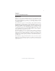
8 Do not over-tighten the screws as this can stress the motherboard. Checking Jumper Settings This section explains how to set jumpers for correct configuration of the motherboard. Setting Jumpers Use the motherboard jumpers to set system configuration options. Jumpers with more than one pin are numbered. When setting the jumpers, ensure that the jumper caps are placed on the correct pins. The illustrations show a 2-pin jumper. When the jumper cap is placed on both pins, the jumper is SHORT.
9 Checking Jumper Settings The following illustration shows the location of the motherboard jumpers. Pin 1 is labeled. Jumper Settings Jumper Type Description Setting (default) 1-2: NORMAL CLR_CMOS 3-pin BIOS_WP 2-pin CLEAR CMOS BIOS PROTECT 2-3: CLEAR 1 Before clearing the CMOS, make sure to turn off the CLR_CMOS system.
10 Installing Hardware Installing the Processor Caution: When installing a CPU heatsink and cooling fan make sure that you DO NOT scratch the motherboard or any of the surfacemount resistors with the clip of the cooling fan. If the clip of the cooling fan scrapes across the motherboard, you may cause serious damage to the motherboard or its components. On most motherboards, there are small surface-mount resistors near the processor socket, which may be damaged if the cooling fan is carelessly installed.
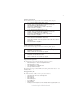
11 CPU Installation Procedure The following illustration shows CPU installation components. A. Read and follow the instructions shown on the sticker on the CPU cap. B. Unload the cap · Use thumb & forefinger to hold the lifting tab of the cap. · Lift the cap up and remove the cap completely from the socket. C. Open the load plate · Use thumb & forefinger to hold the hook of the lever, pushing down and pulling aside unlock it. · Lift up the lever. · Use thumb to open the load plate.
12 Installing Memory Modules This motherboard accomodates four memory modules. It can support four 240-pin DDR2 800/667. The total memory capacity is 16 GB. DDR2 SDRAM memory module table Memory module Memory Bus DDR2 667 DDR2 800 333 MHz 400 MHz You must install at least one module in any of the four slots. Each module can be installed with 4 GB of memory; total memory capacity is 16 GB.
13 Table A: DDR2 (memory module) QVL (Qualified Vendor List) The following DDR2 800/667 memory modules and combination have been tested and qualified for use with this motherboard.
14 Type Size 1 GB DDR2 800 2 GB Vendor Module Name NPC Kingston Kingston Ramaxel Samsung Transcend UMAX Aeneon Aeneon Apacer Apacer A-DATA CORSAIR Micron Micron PSC PSC Qimonda Qimonda Samsung NCPT7AUDR-25M48 KHX6400D2ULK2/2G KVR800D2N5/1G E5108AHSE-8E-E 0705098L1 ZCE7 K4T510830E TQ123PGF8T0709 U2S12D30TP-8E AET03R25DC 0732 AET860UD00-25DC08X AM4B5808CQJS8E 0747D 78.A1GA0.
15 Expansion Slots Installing Add-on Cards The slots on this motherboard are designed to hold expansion cards and connect them to the system bus. Expansion slots are a means of adding or enhancing the motherboard’s features and capabilities. With these efficient facilities, you can increase the motherboard’s capabilities by adding hardware that performs tasks that are not part of the basic system.
16 Follow these instructions to install an add-on card: 1 2 3 Remove a blanking plate from the system case corresponding to the slot you are going to use. Install the edge connector of the add-on card into the expansion slot. Ensure that the edge connector is correctly seated in the slot. Secure the metal bracket of the card to the system case with a screw.
17 Connecting Optional Devices Refer to the following for information on connecting the motherboard’s optional devices: F_AUDIO: Front Panel Audio header This header allows the user to install auxiliary front-oriented microphone and lineout ports for easier access.
18 CD_IN: Analog Audio Input connector Pin 1 2 3 4 Signal Name Function CD_L CD In left channel GND Ground GND CD_R Ground CD In right channel F_USB1~4: Front Panel USB headers The motherboard has four USB ports installed on the rear edge I/O port array. Additionally, some computer cases have USB ports at the front of the case. If you have this kind of case, use auxiliary USB connector to connect the front-mounted ports to the motherboard.
19 COM1: Onboard serial port header Connect a serial port extension bracket to this header to add a second serial port to your system.
20 Installing a SATA Hard Drive About SATA Connectors Your motherboard features six SATA connectors supporting a total of six drives. SATA refers to Serial ATA (Advanced Technology Attachment) is the standard interface for the IDE hard drives which are currently used in most PCs. These connectors are well designed and will only fit in one orientation. Locate the SATA connectors on the motherboard and follow the illustration below to install the SATA hard drives.
21 Installing a Floppy Diskette Drive FDD1: Floppy Disk Connector Connect the single end of the floppy connector to the onboard floppy connector firstly, and then connect the remaining plugs on the other end to the floppy drives correspondingly. You must orient the cable connector so that the pin 1 (color) edge of the cable corresponds to the pin 1 of the I/O port connector.
22 Connecting I/O Devices The backplane of the motherboard has the following I/O ports: PS2 Mouse Use the upper PS/2 port to connect a PS/2 pointing device. PS2 Keyboard Use the lower PS/2 port to connect a PS/2 keyboard. Parallel Port (LPT1) Use LPT to connect printers or other parallel communica (Optional) tions devices. DVI Port Use the DVI port to connect the monitor. VGA1 Port Connect your monitor to the VGA port.
23 Connecting Case Components After you have installed the motherboard into a case, you can begin connecting the motherboard components. Refer to the following: 1 2 3 4 5 Connect the CPU cooling fan cable to CPU_FAN. Connect the system cooling fan connector to SYS_FAN. Connect the case switches and indicator LEDs to the F_PANEL. Connect the standard power supply connector to ATX_POWER1. Connect the auxiliary case power supply connector to ATX12V1.
24 CPU_FANS/SYS_FAN: FAN Power Connector Pin 1 2 3 4 Signal Name GND +12V Sense PWM Function System Ground Power +12V Sensor PWM Users please note that the fan connector supports the CPU cooling fan of 1.1A ~ 2.2A (26.4W max) at +12V. ATX_ POWER1: ATX 24-pin Power Connector Pin Signal Name 1 2 3 4 5 6 7 8 9 +3.3V 10 11 12 +12V Pin 13 14 15 16 17 18 19 20 21 +3.3V Ground +5V Ground +5V Ground PWRGD +5VSB 22 23 24 +12V +3.3V Signal Name +3.
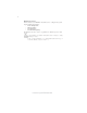
25 Front Panel Header The front panel header (F_PANEL) provides a standard set of switch and LED headers commonly found on ATX or Micro ATX cases.
26 Memo Installing the Motherboard
27 Chapter 3 Using BIOS About the Setup Utility The computer uses the latest “American Megatrends Inc.” BIOS with support for Windows Plug and Play. The CMOS chip on the motherboard contains the ROM setup instructions for configuring the motherboard BIOS. The BIOS (Basic Input and Output System) Setup Utility displays the system’s configuration status and provides you with options to set system parameters.
28 Press the delete key to access the BIOS Setup Utility. CMOS Setup Utility -- Copyright (C) 1985-2008, American Megatrends, Inc.
29 For the purpose of better product maintenance, the manufacture reserves the right to change the BIOS items presented in this manual. The BIOS setup screens shown in this chapter are for reference only and may differ from the actual BIOS. Please visit the manufacture’s website for updated manual. Standard CMOS Setup This option displays basic information about your system. CMOS Setup Utility - Copyright (C) 1985-2008, American Megatrends, Inc.
30 Type (Auto) Use this item to configure the type of the IDE device that you specify. If the feature is enabled, it will enhance hard disk performance by reading or writing more data during each transfer. LBA/Large Mode (Auto) Use this item to set the LAB/Large mode to enhance hard disk performance by optimizing the area the hard disk is visited each time.
31 Advanced Setup This page sets up more advanced information about your system. Handle this page with caution. Any changes can affect the operation of your computer. CMOS Setup Utility - Copyright (C) 1985-2008, American Megatrends, Inc.
32 APIC Mode (Enabled) This item allows you to enable or disable the APCI (Advanced Programmable Interrupt Controller) mode. APIC provides symmetric multi-processing (SMP) for systems, allowing support for up to 60 processors. 1st/2nd/3rd Boot Device (Hard Disk Drive/CD/DVD/1st FLOPPY DRIVE) Use this item to determine the device order the computer used to look for an operating system to load at start-up time.
33 Advanced Chipset Setup This page sets up more advanced information about your system. Handle this page with caution. Any changes can affect the operation of your computer. CMOS Setup Utility - Copyright (C) 1985-2008, American Megatrends, Inc.
34 Integrated Peripherals This page sets up some parameters for peripheral devices connected to the system. CMOS Setup Utility - Copyright (C) 1985-2008, American Megatrends, Inc.
35 Parallel Port IRQ (IRQ7) Use this item to assign IRQ to the parallel port. USB Functions (Enabled) Use this item to enable or disable the USB function. Legacy USB Support (Enabled) Use this item to enable or disable support for legacy USB devices. Setting to Auto allows the system to detect the presence of USB device at startup. If detected, the USB controller legacy mode is enabled. If no USB device is detected, the legacy USB support is disabled. Press to return to the main menu setting page.
36 Resume by Ring (Disabled) An input signal on the serial Ring Indicator (RI) line (in other words, an incoming callon the modem) awakens the system from a soft off state. Resume by PCI/PCI-E/Lan PME (Disabled) These items specify whether the system will be awakened from power saving modeswhen activity or input signal of the specified hardware peripheral or component isdetected. Resume by USB (S3) (Disabled) This item allows users to enable or disable the USB device Walk-up from S3 mode.
37 PC Health Status On motherboards support hardware monitoring, this item lets you monitor the parameters for critical voltages, temperatures and fan speeds. CMOS Setup Utility - Copyright (C) 1985-2008, American Megatrends, Inc. PC Health Status Help Item -=- System Hardware Monitor-=f Smart Fan Function CPU Temperature System Temperature CPU FAN Speed SYS FAN Speed PWR FAN Speed CPU Core VDIMM Press Enter :47°C/116°F : 22°C/71° F : 3479 RPM : N/A : N/A :1.296V : 1.
38 DeltaT (+3) This item specifies the range that controls CPU temperature and keeps it from going so high or so low when smart fan works. SMART Fan Slope PWM value (4 PWM value/°C) This item is used to set the Slope Select PWM of the smart fan. CPU Fan Full Limit Temp. (°C) (69°C) This item is used to set the limit temperature of the smart fan. ECS supports the latest PECI host technology.
39 System Component Characteristics These items display the monitoring of the overall inboard hardware health events, such as System & CPU temperature, CPU & DIMM voltage, CPU & system fan speed,...etc. • • • • CPU/System Temperature CPU/SYS FAN Speed CPU Core VDIMM Warning Temperature (Disabled) This item lets you select the temperature at which you want the system to send out a warning message to the PC speakers when the temperature goes beyond either limit. You can select the temperatures you want.
40 CPU Over-clocking Func. (Disabled) This item decides the CPU over-clocking function/frequencyinstalled in your system. If the over-clocking fails, please turn offthe system power. And then, hold the PageUp key (similar to theClear CMOS function) and turn on the power, the BIOS willrecover the safe default. Auto Detect DIMM/PCI Clk (Enabled) When this item is enabled, BIOS will disable the clock signal of free DIMM/PCI slots.
41 User Password This page helps you install or change a password. CMOS Setup Utility - Copyright (C) 1985-2008, American Megatrends, Inc. User Password User Password : Not Installed Change User Password Help item Press Enter Install or Change the password. mnlk: Move Enter : Select +/-/: Value F10: Save ESC: Exit F1: General Help F9: Load Default Settings User Password (Not Installed) This item indicates whether a user password has been set. If the password has been installed, Installed displays.
42 Updating the BIOS You can download and install updated BIOS for this motherboard from the manufacturer’s Web site. New BIOS provides support for new peripherals, improvements in performance, or fixes for known bugs. Install new BIOS as follows: 1 2 3 4 5 6 7 If your motherboard has a BIOS protection jumper, change the setting to allow BIOS flashing. If your motherboard has an item called Firmware Write Protect in Advanced BIOS features, disable it.
43 Chapter 4 Using the Motherboard Software About the Software CD-ROM The support software CD-ROM that is included in the motherboard package contains all the drivers and utility programs needed to properly run the bundled products. Below you can find a brief description of each software program, and the location for your motherboard version. More information on some programs is available in a README file, located in the same directory as the software.
44 Setup Tab Setup Click the Setup button to run the software installation program. Select from the menu which software you want to install. Browse CD The Browse CD button is the standard Windows command that allows you to open Windows Explorer and show the contents of the support CD. Before installing the software from Windows Explorer, look for a file named README.TXT, INSTALL.TXT or something similar. This file may contain important information to help you install the software correctly.
45 2. Click Next. The following screen appears: 3. Check the box next to the items you want to install. The default options are recommended. 4. Click Next run the Installation Wizard. An item installation screen appears: 5. Follow the instructions on the screen to install the items. 1. Drivers and software are automatically installed in sequence. Follow the onscreen instructions, confirm commands and allow the computer to restart a few times to complete the installation. 2.
46 Method 1. Run Reboot Setup Windows Vista will block startup programs by default when installing drivers after the system restart. You must select taskbar icon Run Blocked Program and run Reboot Setup to install the next driver, until you finish all drivers installation. Method 2. Disable UAC (User Account Control) * For administrator account only. Standard user account can only use Method 1.
47 2. Select Classic View. 3. Set User Account. 4. Select Turn User Account Control on or off and press Continue.
48 5. Disable User Account Control (UAC) to help protect your computer item and press OK, then press Restart Now. Then you can restart your computer and continue to install drivers without running blocked programs. Manual Installation Insert the CD in the CD-ROM drive and locate the PATH.DOC file in the root directory. This file contains the information needed to locate the drivers for your motherboard.
49 HDMI Audio Setting SOP OS: XP system 1. Control Panel-->Sound and Audio Device Properties 2. a. Audio--> Sound playback--> Default device--> HD Auido Output b. Audio--> Sound playback--> Default device--> HDMI Auido Output 3. a. User Playback Audio speaker function working b.
50 OS: Vista system Control Panel--> Soundback--> Sound--> Digital Output Device (HDMI) --> Set Default 1. Volume --> Playback 2.
51 3. Speaker --> Set Default --> OK User Speaker Palyback function working 4. SPDIF-Out --> Set Default --> OK User SPDIF-Out Playback function working This concludes chapter 4.
52 Memo Using the Motherboard Software