Preface Copyright This publication, including all photographs, illustrations and software, is protected under international copyright laws, with all rights reserved. Neither this manual, nor any of the material contained herein, may be reproduced without written consent of the author. Version 2.0 Disclaimer The information in this document is subject to change without notice.
ii Declaration of Conformity This device complies with part 15 of the FCC rules. Operation is subject to the following conditions: • • This device may not cause harmful interference, and This device must accept any interference received, including interference that may cause undesired operation Canadian Department of Communications This class B digital apparatus meets all requirements of the Canadian Interferencecausing Equipment Regulations.
iii TABLE OF CONTENTS Preface i Chapter 1 1 Introducing the Motherboard 1 Introduction......................................................................................1 Feature ..............................................................................................2 Motherboard Components.............................................................4 Chapter 2 7 Installing the Motherboard 7 Safety Precautions...........................................................................
iv Integrated Peripherals.......................................................32 Power Management Setup.................................................33 PCI/PnP Setup...................................................................34 PC Health Status................................................................35 Load Default Settings........................................................38 Load Non Disk...................................................................39 Supervisor Password......
1 Chapter 1 Introducing the Motherboard Introduction Thank you for choosing the IC43T-A2 motherboard. This motherboard is a high performance, enhanced function motherboard designed to support the LGA775 socket Intel® Core™ 2 Extreme/Core™ 2 Quad/Core™ 2 Duo/Pentium® Dual-Core/Celeron® Dual-Core/Celeron® 400 series processors for high-end business or personal desktop markets. The motherboard incorporates the Intel Eaglelake P43 Northbridge (NB) and Intel ICH10 Southbridge (SB) chipsets.
2 Feature Processor This motherboard uses an LGA775 type of Intel® Core™ 2 Extreme/Core™ 2 Quad/ Core™ 2 Duo/Pentium® Dual-Core/Celeron® Dual-Core/Celeron® 400 series that carries the following features: • • Accommodates Intel® Core™ 2 Extreme/Core™ 2 Quad/Core™ 2 Duo/ Pentium® Dual-Core/Celeron® Dual-Core/Celeron® 400 series processors Supports a system bus (FSB) of 1333/1066/800 MHz Chipset The P43 Northbridge (NB) and ICH10 Southbridge (SB) chipsets are based on an innovative and scalable architectur
3 Onboard LAN • • • Supports PCI Express™ 1.1 Integrated 10/100/1000 transceiver Wake-on-LAN and remote wake-up support Expansion Options The motherboard comes with the following expansion options: • • • • One PCI Express x16 slot for Graphics Interface Three PCI Express x1 slots Two 32-bit PCI v2.
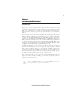
4 Motherboard Components Introducing the Motherboard
5 Table of Motherboard Components LABEL CO MPO NENTS LGA775 socket Intel® Core™ 2 Extreme/ Core™ 2 Quad/Core™ 2 Duo/Pentium ® Dual-Core/ 1. CPU Socket Celeron ® Dual-Core/Celeron ® 400 series processors 2. DDR3_1~4 240-pin DDR3 SDRAM slots 3. CPU_FAN CPU cooling fan connector 4. AT X_POWER Standard 24-Pin AT X Power connector 5. SAT A1~6 Serial AT A connectors 6. F_PANEL Front Panel Switch/LED header 7. F_USB1~3 Front Panel USB headers 8. USBPWR_F1~2 Front Panel USB Power Select jumpers 9.
6 Memo Introducing the Motherboard
7 Chapter 2 Installing the Motherboard Safety Precautions • • • • • Follow these safety precautions when installing the motherboard Wear a grounding strap attached to a grounded device to avoid damage from static electricity Discharge static electricity by touching the metal case of a safely grounded object before working on the motherboard Leave components in the static-proof bags they came in Hold all circuit boards by the edges.
8 Do not over-tighten the screws as this can stress the motherboard. Checking Jumper Settings This section explains how to set jumpers for correct configuration of the motherboard. Setting Jumpers Use the motherboard jumpers to set system configuration options. Jumpers with more than one pin are numbered. When setting the jumpers, ensure that the jumper caps are placed on the correct pins. The illustrations show a 2-pin jumper. When the jumper cap is placed on both pins, the jumper is SHORT.
9 Checking Jumper Settings The following illustration shows the location of the motherboard jumpers. Pin 1 is labeled. Jumper Settings Jumper Type Description CLR_CMOS 3-pin CLEAR CMOS Rear USB/PS2 USBPWR_R1 3-pin Power Select Jumper Setting (default) 1-2: NORMAL 2-3: CLEAR Before clearing the 1 CMOS, make sure to turn the system off. CLR_CMOS 1 1-2: VCC 2-3: 5VSB USBPWR_R1 Front Panel USBPWR_F1~2 3-pin USB Power Select Jumper 1-2: VCC 2-3: 5VSB 1 USBPWR_F1~2 1.
10 Installing Hardware Installing the Processor Caution: When installing a CPU heatsink and cooling fan make sure that you DO NOT scratch the motherboard or any of the surface-mount resistors with the clip of the cooling fan. If the clip of the cooling fan scrapes across the motherboard, you may cause serious damage to the motherboard or its components. On most motherboards, there are small surface-mount resistors near the processor socket, which may be damaged if the cooling fan is carelessly installed.
11 CPU Installation Procedure The following illustration shows CPU installation components. A. Read and follow the instructions shown on the sticker on the CPU cap. B. Unload the cap · Use thumb & forefinger to hold the lifting tab of the cap. · Lift the cap up and remove the cap completely from the socket. C. Open the load plate · Use thumb & forefinger to hold the hook of the lever, pushing down and pulling aside unlock it. · Lift up the lever. · Use thumb to open the load plate.
12 Installing Memory Modules This motherboard accommodates four memory modules. It can support four 240-pin DDR3 1066/800. The total memory capacity is 8 GB*. DDR3 SDRAM memory module table Memory module Memory Bus DDR3 800 400 MHz DDR3 1066 533 MHz You must install at least one module in any of the four slots. The total memory capacity is up to 8 GB*.
13 Table A: DDR3 (memory module) QVL (Qualified Vendor List) The following DDR3 1066/800 memory modules have been tested and qualified for use with this motherboard.
14 Type Size Vendor Module Name A-data AD31333001GOU(AD63I1A08) AHU02GFA33C9N1C Apacer Hynix 1GB DDR3 1333 2 GB HMT112U6AFP8C-H9N0 AA KingMax Kingston FLFD45F-B8KG9 NAES KVR1333D3N9/1G Micron Ramaxel MT8JTF12864AY-1G4D1 RMR1810KD48E7F-1333 Samsung Samsung M378B2873EH1-CH9 M378B2873DZ1-CH9 A-data Elixir AD31333002GOU(AD63I1B16) M2F2G64CB8HA4N-CG 0903.
15 Expansion Slots Installing Add-on Cards The slots on this motherboard are designed to hold expansion cards and connect them to the system bus. Expansion slots are a means of adding or enhancing the motherboard’s features and capabilities. With these efficient facilities, you can increase the motherboard’s capabilities by adding hardware that performs tasks that are not part of the basic system.
16 Follow these instructions to install an add-on card: 1 2 3 Remove a blanking plate from the system case corresponding to the slot you are going to use. Install the edge connector of the add-on card into the expansion slot. Ensure that the edge connector is correctly seated in the slot. Secure the metal bracket of the card to the system case with a screw.
17 Connecting Optional Devices Refer to the following for information on connecting the motherboard optional devices F_AUDIO: Front Panel Audio header This header allows the user to install auxiliary front-oriented microphone and lineout ports for easier access.
18 F_USB1~3: Front Panel USB headers The motherboard has four USB ports installed on the rear edge I/O port array. Additionally, some computer cases have USB ports at the front of the case. If you have this kind of case, use auxiliary USB connector to connect the front-mounted ports to the motherboard.
19 Installing a SATA Hard Drive About SATA Connectors Your motherboard features six SATA connectors supporting a total of six drives. SATA refers to Serial ATA (Advanced Technology Attachment) is the standard interface for the IDE hard drives which are currently used in most PCs. These connectors are well designed and will only fit in one orientation. Locate the SATA connectors on the motherboard and follow the illustration below to install the SATA hard drives.
20 Connecting I/O Devices The backplane of the motherboard has the following I/O ports: PS2 Mouse Use the upper PS/2 port to connect a PS/2 pointing device. PS2 Keyboard Use the lower PS/2 port to connect a PS/2 keyboard. Serial Port (COM) Use the COM port to connect serial devices such as mice or fax/modems. USB Ports Use the USB ports to connect USB devices. LAN Port Connect an RJ-45 jack to the LAN port to connect your computer to the network.
21 Connecting Case Components After you have installed the motherboard into a case, you can begin connecting the motherboard components. Refer to the following: 1 Connect the CPU cooling fan cable to CPU_FAN. 2 Connect the system cooling fan connector to SYS_FAN. 3 Connect the standard power supply connector to ATX_POWER. 4 Connect the auxiliary case power supply connector to ATX12V. 5 Connect the case switches and indicator LEDs to the F_PANEL. 6 Connect the case speaker cable to SPK.
22 CPU_FAN: CPU Cooling FAN Power Connector Pin 1 2 3 4 Signal Name Function System Ground Power +12V Sensor CPU FAN control GND +12V Sense Control Users please note that the fan connector supports the CPU cooling fan of 1.1A ~ 2.2A (26.4W max) at +12V. SYS_FAN: System cooling FAN Power Connector Pin 1 2 3 Signal Name Function System Ground Power +12V Sensor GND +12V Sense ATX_POWER: ATX 24-pin Power Connector Pin 1 2 3 4 5 6 7 8 9 10 11 12 Signal Name Pin 13 14 15 16 17 18 19 20 21 +3.
23 Front Panel Header The front panel header (F_PANEL) provides a standard set of switch and LED headers commonly found on ATX or Micr ATX cases.
24 Memo Installing the Motherboard
25 Chapter 3 Using BIOS About the Setup Utility The computer uses the latest “American Megatrends Inc. ” BIOS with support for Windows Plug and Play. The CMOS chip on the motherboard contains the ROM setup instructions for configuring the motherboard BIOS. The BIOS (Basic Input and Output System) Setup Utility displays the system’s configuration status and provides you with options to set system parameters.
26 Press the delete key to access the BIOS Setup Utility. CMOS Setup Utility -- Copyright (C) 1985-2008, American Megatrends, Inc. f Standard CMOS Setup f Advanced Setup f Advanced Chipset Setup f Integrated Peripherals f Power Management Setup f PCI/PnP Setup f PC Health Status f M.I.B.
27 Using BIOS When you start the Setup Utility, the main menu appears. The main menu of the Setup Utility displays a list of the options that are available. A highlight indicates which option is currently selected. Use the cursor arrow keys to move the highlight to other options. When an option is highlighted, execute the option by pressing . Some options lead to pop-up dialog boxes that prompt you to verify that you wish to execute that option.
28 For the purpose of better product maintenance, the manufacture reserves the right to change the BIOS items presented in this manual. The BIOS setup screens shown in this chapter are for reference only and may differ from the actual BIOS. Please visit the manufacture’s website for updated manual. Standard CMOS Setup This option displays basic information about your system. CMOS Setup Utility -- Copyright (C) 1985-2008, American Megatrends, Inc.
29 Type (Auto) Use this item to configure the type of the IDE device that you specify. If the feature is enabled, it will enhance hard disk performance by reading or writing more data during each transfer. LBA/Large Mode (Auto) Use this item to set the LBA/Large mode to enhance hard disk performance by optimizing the area the hard disk is visited each time.
30 Advanced Setup This page sets up more advanced information about your system. Handle this page with caution. Any changes can affect the operation of your computer. CMOS Setup Utility - Copyright (C) 1985-2008, American Megatrends, Inc.
31 Boot Up Numlock Status (On) This item defines if the keyboard Num Lock key is active when your system is started. APIC Mode (Enabled) This item allows you to enable or disable the APCI (Advanced Programmable Interrupt Controller) mode. APIC provides symmetric multi-processing (SMP) for systems, allowing support for up to 60 processors. 1st/2nd3rd Boot Device (Hard Drive/CD/DVD/Removable Dev.
32 Integrated Peripherals This page sets up some parameters for peripheral devices connected to the system. CMOS Setup Utility - Copyright (C) 1985-2008, American Megatrends, Inc.
33 Power Management Setup This page sets up some parameters for system power management operation. CMOS Setup Utility - Copyright (C) 1985-2008, American Megatrends, Inc.
34 Resume on RTC Alarm (Disabled) The system can be turned off with a software command. If you enable this item, the system can automatically resume at a fixed time based on the system’s RTC (realtime clock). Use the items below this one to set the date and time of the wake-up alarm. You must use an ATX power supply in order to use this feature. Press to return to the main menu setting page.
35 PC Health Status On motherboards support hardware monitoring, this item lets you monitor the parameters for critical voltages, temperatures and fan speeds. CMOS Setup Utility - Copyright (C) 1985-2008, American Megatrends, Inc. PC Health Status -=- System Hardware Monitor-=Smart Fan Function System Temperature CPU FAN Speed CPU Core VDIMM f Help Item Press Enter : 33°C/91°F : 2934 RPM : 1.216 V : 1.552 V -=- PECI Mode -=Offset to TCC Activation Temp.
36 CMOS Setup Utility - Copyright (C) 1985-2008, American Megatrends, Inc. Smart Fan Function Help Item CPU SMART FAN Control SMART Fan Mode SMART Fan start PWM value SMART Fan start PWM TEMP (° C) DeltaT SMART Fan Slope PWM value CPU Fan Full Speed Offset (-) Enabled Quiet 15 29 +3 5 7 Options Normal: auto adjusts depending on the CPU temperature. Quiet: auto minimizes fan speed for quiet environment operation. Silent: auto restricts fan speed to make system more quietly.
37 CMOS Setup Utility - Copyright (C) 1985-2008, American Megatrends, Inc. Smart Fan Function CPU SMART FAN Control SMART Fan Mode SMART Fan start PWM value SMART Fan start PWM TEMP (° C) DeltaT SMART Fan Slope PWM value CPU Fan Full Speed Offset (-) Enabled Manual 28 32 +3 4 7 Help Item Options Normal: auto adjusts depending on the CPU temperature. Quiet: auto minimizes fan speed for quiet environment operation. Silent: auto restricts fan speed to make system more quietly.
38 M.I.B. II (MB Intelligent BIOS II) This page enables you to set the clock speed and system bus for your system. The clock speed and system bus are determined by the kind of processor you have installed in your system. CMOS Setup Utility - Copyright (C) 1985-2008, American Megatrends, Inc. M.I.B.II (MB Intelligent BIOS II) Performance Level DRAM Frequency Configure DRAM Timing by SPD DRAM Command Rate CPU Over-clocking Func.
39 Spread Spectrum (Enabled) If you enable spread spectrum, it can significantly reduce the EMI (Electro-Magnetic Interference) generated by the system. CPU Voltage (Disabled) This item enable or disable users to adjust the CPU voltage. NB Voltage (Disabled) This item enable or disable users to adjust the North Bridge voltage. DIMM Voltage (Disabled) This item enable or disable users to adjust the DDR memory voltage. CPU VTT Voltage (1.11V) This item allows users to adjust the CPU VTT voltage.
40 Load Non Disk 1. The default value of the item “Onboard LAN Boot ROM” is “ Disabled” accordingly since the item “Load Non Disk” is set to “Disabled”. CMOS Setup Utility - Copyright (C) 1985-2008, American Megatrends, Inc.
41 4. Then the default value of the item “Onboard LAN Boot ROM” changed to “Enabled”. CMOS Setup Utility - Copyright (C) 1985-2008, American Megatrends, Inc.
42 Supervisor Password This page helps you install or change a password. CMOS Setup Utility - Copyright (C) 1985-2008, American Megatrends, Inc. Supervisor Password Supervisor Password Help Item :Installed Change Supervisor Password Security Check Press Enter Setup mnlk : Move Install or Change the password. Enter : Select +/-/: Value F10: Save F1:General Help F9: Load Default Settings ESC: Exit Supervisor Password (Not Installed) This item indicates whether a supervisor password has been set.
43 User Password This page helps you install or change a password. CMOS Setup Utility - Copyright (C) 1985-2008, American Megatrends, Inc. User Password User Password Help Item : Not Installed Change Supervisor Password Press Enter mnlk : Move Install or Change the password. Enter : Select +/-/: Value F10: Save F1:General Help F9: Load Default Settings ESC: Exit User Password (Not Installed) This item indicates whether a user password has been set.
44 Updating the BIOS You can download and install updated BIOS for this motherboard from the manufacturer’s Web site. New BIOS provides support for new peripherals, improvements in performance, or fixes for known bugs. Install new BIOS as follows: 1 If your motherboard has a BIOS protection jumper, change the setting to allow BIOS flashing. 2 If your motherboard has an item called Firmware Write Protect in Advanced BIOS features, disable it. (Firmware Write Protect prevents BIOS from being overwritten.
45 Chapter 4 Using the Motherboard Software About the Software DVD-ROM/CD-ROM The support software DVD-ROM/CD-ROM that is included in the motherboard package contains all the drivers and utility programs needed to properly run the bundled products. Below you can find a brief description of each software program, and the location for your motherboard version. More information on some programs is available in a README file, located in the same directory as the software.
46 Drivers Tab Setup Click the Setup button to run the software installation program. Select from the menu which software you want to install. Browse CD The Browse CD button is the standard Windows command that allows you to open Windows Explorer and show the contents of the support disk. Before installing the software from Windows Explorer, look for a file named README.TXT or something similar. This file may contain important information to help you install the software correctly.
47 2. Click Next. The following screen appears: 3. Check the box next to the items you want to install. The default options are recommended. 4. Click Next run the Installation Wizard. An item installation screen appears: 5. Follow the instructions on the screen to install the items. Drivers and software are automatically installed in sequence. Follow the onscreen instructions, confirm commands and allow the computer to restart a few times to complete the installation.
48 Windows Vista/7 will appear below UAC (User Account Control) message after the system restart. You must select “Allow” to install the next driver. Continue this process to complete the drivers installation. Manual Installation Insert the disk in the DVD-ROM/CD-ROM drive and locate the PATH.DOC file in the root directory. This file contains the information needed to locate the drivers for your motherboard.
49 Chapter 5 Setting Up eJIFFY Introduction eJIFFY is a fast boot program under Linux. Instead of waiting Windows O.S to start execution, eJIFFY is ready to provide users the instant enjoyment on web browsing, photo review and online chat just within several seconds after boot up. Note: eJIFFY is ECS optional feature utility corresponding to the DVD activation and BIOS setup. Please check the hard copy user’s guide or product color-box to see if the model has embodded eJIFFY feature.
50 Installation and BIOS Setup DVD Activation Finish the DVD utility setup, and then set the BIOS to complete eJIFFY activation. 1. Insert ECS software utility DVD and enter below “Utilities” screen. Click eJIFFY feature item to install. 2. Follow the onscreen instructions to finish eJIFFY setup.
51 3. After setting up eJIFFY under Windows, you can switch eJIFFY display/keyboard language from English to your local language. The changes will be applied after rebooting. Note: The keyboard language selection list offers several more regional keyboard setups to switch with the default English typing. Please refer to the usage FAQ for more tips.
52 4. Restart your computer after eJIFFY installation. Press or click the BIOS Setup button on the post screen to enter the BIOS setup page after boot up. 5. And then enter the Advanced Setup page to enable the item ECS eJIFFY Function. Press F10 to save the configuration and exit. Restart your computer. Note: 1. eJIFFY is available in SATA/IDE/AHCI mode. It does not support RAID configuration and the onboard 34-pin floppy drives. 2. Please refer to ECS website for new eJIFFY application updates.
53 Entering eJIFFY The post screen appears within several seconds after boot up and it has three buttons on it, Operating system, eJIFFY and BIOS Setup. Click to enter the normal OS you have installed such as Windows. Click to enter eJIFFY OS. Click to set the BIOS. If you click eJIFFY, the following screen will appear. And If you make no choice it will enter the normal OS automatically after ten seconds.
54 Feature Icons The following illustration shows the main feature icons that eJIFFY provides on the menu. eWeb: Firefox for web browsing/webmail and watching flash video. ePix: Photo viewing. ePal: On-line chat tool to use the most popular IMs in the world. (MSN, ICQ , AIM, etc.) Shows ePal on-line connection status. Shut Down/Restart: Ends your session and turns off the computer./Ends your session and restart the computer.. Click once to connect the storage disk to your computer.
55 Usage FAQ Language Control Panel: Besides setting English as the default interface, eJIFFY offers multi-language displays and keyboard settings for languageswitch. Open the language control panel to select a preferable language setting. Keyboard Language Setup Step1. Click to open the language control panel. Step 2: Click “Keyboard Language” icon to open the keyboard selection list, which offers several regional keyboard settings besides default English keyboard.
56 Click to enable all possible language inputs you want to apply, and click “Apply”: Move your mouse pointer on the text box and press Ctrl+Space. The language bar will then appear as follows. Click the language bar here.
57 How to change display language? Open the Language Control Panel and click to show the display language list. Check your desired display language. Your selected display language will be applied after rebooting. Note: Details about eJIFFY please refer to eJIFFY in disk.
58 Memo Setting Up eJIFFY
59 Chapter 6 Trouble Shooting Start up problems during assembly After assembling the PC for the first time you may experience some start up problems. Before calling for technical support or returning for warranty, this chapter may help to address some of the common questions using some basic troubleshooting tips. a) System does not power up and the fans are not running. 1.Disassemble the PC to remove the VGA adaptor card, DDR memory, LAN, USB and other peripherals including keyboard and mouse.
60 c) The PC suddenly shuts down while booting up. 1. The CPU may experience overheating so it will shutdown to protect itself. Ensure the CPU fan is working properly. 2. From the BIOS setting, try to disable the Smartfan function to let the fan run at default speed. Doing a Load Optimised Default will also disable the Smartfan. Start up problems after prolong use After a prolong period of use your PC may experience start up problems again.
If fail, contact RMA CLR CMOS and restart. Yes Halt at POST screen? Yes Check if monitor has display Yes Check if Power Supply Unit (PSU) is working Power Bu on is pressed but PC fails to start. CMOS setup error, - need to CLRCMOS. HDD problem.
62 Memo Trouble Shooting