Preface Copyright This publication, including all photographs, illustrations and software, is protected under international copyright laws, with all rights reserved. Neither this manual, nor any of the material contained herein, may be reproduced without written consent of the author. Version 3.0 Disclaimer The information in this document is subject to change without notice.
ii Declaration of Conformity This device complies with part 15 of the FCC rules. Operation is subject to the following conditions: • • This device may not cause harmful interference, and This device must accept any interference received, including interference that may cause undesired operation Canadian Department of Communications This class B digital apparatus meets all requirements of the Canadian Interferencecausing Equipment Regulations.
iii TABLE OF CONTENTS Preface i Chapter 1 1 Introducing the Motherboard 1 Introduction......................................................................................1 Feature...............................................................................................2 Motherboard Components.............................................................4 Chapter 2 7 Installing the Motherboard 7 Safety Precautions...........................................................................
iv Integrated Peripherals.......................................................36 Power Management Setup.................................................37 PNP/PCI Setup..................................................................39 PC Health Status................................................................39 Frequency/Voltage Control ...............................................41 Load Default Settings.........................................................42 Supervisor Password.............
1 Chapter 1 Introducing the Motherboard Introduction Thank you for choosing the GeForce6100PM-M2 motherboard. This motherboard is a high performance, enhanced function motherboard that supports socket for AMD PhenomTM II/PhenomTM processor (socket AM2+)/AMD AthlonTM 64 X2 DualCore/AthlonTM 64/SempronTM processors for high-end business or personal desktop markets. This motherboard is based on NVIDIA® ΜCP61 Premium media and communications processor (MCP) for best desktop platform solution.
2 Feature Processor This motherboard uses a socket AM2+/AM2 that carries the following features: • Accommodates AMD PhenomTM II/PhenomTM processor (socket AM2+) AMD AthlonTM 64 X2 Dual-Core/AthlonTM 64/SempronTM processors • Supports up to 2000 MT/s HyperTransportTM (HT) interface Speeds HyperTransport TM Technology is a point-to-point link between two devices, it enables integrated circuits to exchange information at much higher speeds than currently available interconnect technologies.
3 Onboard LAN The onboard LAN provides the following features: • • • 10BASE-T/100BASE-TX IEEE 802.3u fast Ethernrt transceiver Low-power mode MII and 7-wire serial interface Expansion Options : motherboard comes with the following expansion options: The • • • • • • One PCI Express x16 slot for Graphics Interface One PCI Express x1 slot Two 32-bit PCI v2.
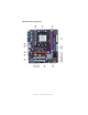
4 Motherboard Components Introducing the Motherboard
5 Table of Motherboard Components LABEL 1. CPU Socket CO MPO NENTS Socket for AMD Phenom TM II/Phenom TM processor (socket AM2+)/ AMD Athlon TM 64 X2 Dual-Core/Athlon TM 64/Sempron TM processors 2. DIMM1~2 240-pin DDR2 SDRAM slots 3. FDD Floppy disk drive connector 4. PWR1 Standard 24-Pin AT X Power connector 5. IDE1 Primary IDE connector 6. SPK1 Speaker header 7. SAT A1~4 Serial AT A connectors 8. IR1* Infrared header 9. CLR_CMOS Clear CMOS jumper 10.
6 Memo Introducing the Motherboard
7 Chapter 2 Installing the Motherboard Safety Precautions • • • • • Follow these safety precautions when installing the motherboard Wear a grounding strap attached to a grounded device to avoid damage from static electricity Discharge static electricity by touching the metal case of a safely grounded object before working on the motherboard Leave components in the static-proof bags they came in Hold all circuit boards by the edges.
8 Do not over-tighten the screws as this can stress the motherboard. Checking Jumper Settings This section explains how to set jumpers for correct configuration of the motherboard. Setting Jumpers Use the motherboard jumpers to set system configuration options. Jumpers with more than one pin are numbered. When setting the jumpers, ensure that the jumper caps are placed on the correct pins. The illustrations show a 2-pin jumper. When the jumper cap is placed on both pins, the jumper is SHORT.
9 Checking Jumper Settings The following illustration shows the location of the motherboard jumpers. Pin 1 is labeled. Jumper Settings Jumper Type Description Setting (default) CLR_CMOS 3-pin CLEAR CMOS 1-2: NORMAL 1 2-3: CLEAR Before clearing the CMOS, make sure to turn the system off. CLR_CMOS Rear USB/PS2 USBPWR_R 3-pin Power Select Jumper 1-2: VCC5 2-3: VCC5_DUAL 1 USBPWR_R Front Panel USBPWR_F 3-pin USB Power Select Jumper 1-2: VCC5 2-3: VCC5_DUAL 1 USBPWR_F 1.
10 Installing Hardware Installing the Processor Caution: When installing a CPU heatsink and cooling fan make sure that you DO NOT scratch the motherboard or any of the surface-mount resistors with the clip of the cooling fan. If the clip of the cooling fan scrapes across the motherboard, you may cause serious damage to the motherboard or its components. On most motherboards, there are small surface-mount resistors near the processor socket, which may be damaged if the cooling fan is carelessly installed.
11 CPU Installation Procedure The following illustration shows CPU installation components. 1 2 3 4 5 6 Unhook the locking lever of the CPU socket. Pull the locking lever away from the socket and raising it to the upright position. Match the pin1 corner marked as the beveled edge on the CPU with the pin1 corner on the socket. Insert the CPU into the socket. Do not use force. Push the locking lever down and hook it under the latch on the edge of socket. Apply thermal grease to the top of the CPU.
12 Installing Memory Modules This motherboard accommodates two 240-pin unbuffered DIMMs and supports DDR2 800/667/533/400 DDR2 SDRAM. You must install at least one module in any of the two slots. The total memory capacity is up to 16 GB. DDR2 SDRAM memory module table Memory module Memory Bus DDR2 400 200 MHz DDR2 533 266 MHz DDR2 667 333 MHz DDR2 800 400 MHz Do not remove any memory module from its antistatic packaging until you are ready to install it on the motherboard.
13 Table A: DDR2 (memory module) QVL (Qualified Vendor List) The following DDR2 memory modules have been tested and qualified for use with this motherboard. Type DDR2 533 Size Vendor Module Name 512 MB Samsung PC2-4200U-4444-10-B1 1 GB A-DATA A-DATA/Vitesta/1GB/DS 512 MB Apacer 78.91G92.9K5 Micron MT4HTF 6464AY-667E1 PSC AL6E8E63J-6E1 Ramxel RML1520M38D6F-667 Samsung PC2-5300U-555-12-D3 Apacer 1 GB AU01GE667C5KBGC 78.01G9O.
14 Type Size 512 MB Vendor Module Name Kingston KVR800D 2N 5/512 1.8V 9905315-019.A02LF Micron MT8HT F6464AY-80ED4 Qimonda HYS72T64000HU- 2.5-B A-DATA M2GVD6G3I41P0U1E5E Aeneon AET760UD00-30DB97X AET760UD00-25DC08X AU01GE800C5KBGC Apacer 78.01GAO.9K5 APOGEE AU1G082-800P000 Geil GEIL MILLENARY/Geil/GL2L64M088BA18H 78.01GA0.9L5 1 GB Infinity 04701G16CZ 5U2G Kingston KVR800D2N5/1G 1.8V 9905316-054.
15 Expansion Slots Installing Add-on Cards The slots on this motherboard are designed to hold expansion cards and connect them to the system bus. Expansion slots are a means of adding or enhancing the motherboard’s features and capabilities. With these efficient facilities, you can increase the motherboard’s capabilities by adding hardware that performs tasks that are not part of the basic system.
16 Follow these instructions to install an add-on card: 1 2 3 Remove a blanking plate from the system case corresponding to the slot you are going to use. Install the edge connector of the add-on card into the expansion slot. Ensure that the edge connector is correctly seated in the slot. Secure the metal bracket of the card to the system case with a screw.
17 Connecting Optional Devices Refer to the following for information on connecting the motherboard’s optional devices: F_AUDIO: Front Panel Audio header (optional) This header allows the user to install auxiliary front-oriented microphone and lineout ports for easier access.
18 IR1: Infrared header (optional) The motherboard supports an Infrared (IR1) data port. Infrared ports allow the wireless exchange of information between your computer and similarly equipped devices such as printers, laptops, Personal Digital Assistants (PDAs), and other computers.
19 CD_IN: Analog Audio Input connector Pin 1 2 3 4 Signal Name Function CD_L CD In left channel GND Ground GND CD_R Ground CD In right channel Installing the Motherboard
20 Installing a Hard Disk Drive/CD-ROM/SATA Hard Drive This section describes how to install IDE devices such as a hard disk drive and a CDROM drive. About IDE Devices Your motherboard has one IDE interface. An IDE ribbon cable supporting two IDE devices is bundled with the motherboard. You must orient the cable connector so that the pin1 (color) edge of the cable corresponds to the pin 1 of the I/O port connector.
21 Refer to the illustration below for proper installation: 1 2 3 Attach either cable end to the connector on the motherboard. Attach the other cable end to the SATA hard drive. Attach the SATA power cable to the SATA hard drive and connect the other end to the power supply. This motherboard does not support the “Hot-Plug” function.
22 Connecting I/O Devices The backplane of the motherboard has the following I/O ports: PS2 Mouse Use the upper PS/2 port to connect a PS/2 pointing device. PS2 Keyboard Use the lower PS/2 port to connect a PS/2 keyboard. Parallel Port (LPT) (optional) Use LPT to connect printers or other parallel communications devices. Serial Port (COM1) Use the COM port to connect serial devices such as mice or fax/modems. VGA1 Port Connect your monitor to the VGA port. USB Ports .
23 Connecting Case Components After you have installed the motherboard into a case, you can begin connecting the motherboard components. Refer to the following: 1 2 3 4 5 6 Connect the CPU cooling fan cable to CPU_FAN. Connect the system cooling fan connector to SYS_FAN. Connect the standard power supply connector to PWR1. Connect the auxiliary case power supply connector to PWR2. Connect the case switches and indicator LEDs to the PANEL1. Connec the case speaker cable to SPK1.
24 CPU_FAN: FAN Power Connector Pin 1 2 3 4 Signal Name Function System Ground Power +12V Sensor CPU FAN control GND +12V Sense Control Users please note that the fan connector supports the CPU cooling fan of 1.1A ~ 2.2A (26.4W max) at +12V. SYS_FAN: System Cooling FAN Power Connector Pin 1 2 3 Signal Name Function System Ground Power +12V Sensor GND +12V Sense PWR1: ATX 24-pin Power Connector Pin 1 2 3 4 5 6 7 8 9 10 11 12 Signal Name Pin 13 14 15 16 17 18 19 20 21 +3.3V +3.
25 SPK1: Internal speaker header Pin Signal Name 1 2 3 4 VCC Key GND Signal Front Panel Header The front panel header (PANEL1) provides a standard set of switch and LED headers commonly found on ATX or Micro ATX cases.
26 Memo Installing the Motherboard
27 Chapter 3 Using BIOS About the Setup Utility The computer uses the latest “American Megatrends Inc.” BIOS with support for Windows Plug and Play. The CMOS chip on the motherboard contains the ROM setup instructions for configuring the motherboard BIOS. The BIOS (Basic Input and Output System) Setup Utility displays the system’s configuration status and provides you with options to set system parameters.
28 Press the delete key to access the BIOS Setup Utility. CMOS Setup Utility -- Copyright (C) 1985-2005, American Megatrends, Inc. f Standard CMOS Setup f Advanced Setup f Advanced Chipset Setup f Integrated Peripherals f Power Management Setup f PCI/PnP Setup f PC Health Status fFrequency/Voltage Control Load Default Settings fSupervisor Password fUser Password Save & Exit Setup Exit Without Saving mnlk : Move Enter : Select +/-/: Value F10: Save F1:General Help F9: Optimized Defaults ESC: Exit v02.
29 Using BIOS When you start the Setup Utility, the main menu appears. The main menu of the Setup Utility displays a list of the options that are available. A highlight indicates which option is currently selected. Use the cursor arrow keys to move the highlight to other options. When an option is highlighted, execute the option by pressing . Some options lead to pop-up dialog boxes that prompt you to verify that you wish to execute that option.
30 For the purpose of better product maintenances, we reserve the right to change the BIOS items presented in the manual. The BIOS setup screens shown in this chapter are for reference only. Please visit our website for updated manual. Standard CMOS Setup This option displays basic information about your system. CMOS Setup Utility -- Copyright (C) 1985-2005, American Megatrends, Inc.
31 f Primary IDE Master/Slave, SATA 1~4 Your computer has one IDE channel which can be installed with one or two devices (Master and Slave). In addition, this motherboard supports four SATA channels and each channel allows one SATA device to be installed. Use these items to configure each device on the IDE channel. CMOS SETUP UTILITY – Copyright (C) 1985-2005, American Megatrends, Inc.
32 IDE BusMaster (Enabled) This item enables or disables the DMA under DOS mode. We recommend you to leave this item at the default value. Drive A (1..44 MB 31/2”) This item defines the characteristics of any diskette drive attached to the system. You can connect one or two diskette drives. Press to return to the main menu setting page.
33 Advanced Setup This page sets up more advanced information about your system. Handle this page with caution. Any changes can affect the operation of your computer. CMOS Setup Utility - Copyright (C) 1985-2005, American Megatrends, Inc.
34 fHard Disk Drives (Press Enter) Scroll to this item and press to view the following screen: CMOS Setup Utility - Copyright (C) 1985-2005, American Megatrends, Inc. Hard Disk Drives Hard Disk Drives Help Item 1st Drive ST340824A Specifies the boot sequence from the available devices. mnlk: Move Enter : Select +/-/: Value F10: Save ESC: Exit F1:General Help F9: Optimized Defaults Press to return to the Advanced setup page.
35 Advanced Chipset Setup This page sets up more advanced information about your system. Handle this page with caution. Any changes can affect the operation of your computer. CMOS Setup Utility - Copyright (C) 1985-2005, American Megatrends, Inc.
36 Integrated Peripherals This page sets up some parameters for peripheral devices connected to the system. CMOS Setup Utility - Copyright (C) 1985-2005, American Megatrends, Inc.
37 Onboard AUDIO Function (Auto) Use this item to enable or disable the onboard audio device. OnBoard LAN Function (Auto) Use this item to enable or disable the onboard LAN function. OnBoard LAN Boot ROM (Disabled) Use this item to enable or disable the booting from the onboard LAN or a network add-in card with a remote boot ROM installed. Serial Port1 Address (3F8/IRQ4) Use this item to enable or disable the onboard COM1 serial port, and to assign a port address.
38 ACPI Suspend Type (S3(STR)) Use this item to define how your system suspends. In the default, S3, the suspend mode is a suspend to RAM, i.e, the system shuts down with the exception of a refresh current to the system memory. PWRON After PWR-Fail (Power Off) This item enables your computer to automatically restart or return to its operating status. Soft-Off By PWR-BTTN (Instant Off) Under ACPI (Advanced Configuration and Power management Interface) you can create a software power down.
39 PCI / PnP Setup This page sets up some parameters for devices installed on the PCI bus and those utilizing the system plug and play capability. CMOS Setup Utility - Copyright (C) 1985-2005, American Megatrends, Inc.
40 f Smart Fan Function Scroll to this item and press to view the following screen: CMOS Setup Utility - Copyright (C) 1985-2005, American Megatrends, Inc. Smart Fan Function SMART Fan Control SMART Fan Start PWM value SMART Fan start TEMP.
41 System Component Characteristics These items display the monitoring of the overall inboard hardware health events, such as System & CPU temperature, CPU & DIMM voltage, CPU & system fan speed,...etc. • CPU Core • VDIMM • CPU Fan Speed • CPU Tcontrol • System Temperature Press to return to the main menu setting page. Frequency/Voltage Control This page enables you to set the clock speed and system bus for your system.
42 Load Default Settings This option opens a dialog box to ask if you are sure to install optimized defaults or not. You select [OK], and then , the Setup Utility loads all default values; or select [Cancel], and then , the Setup Utility does not load default values. Supervisor Password This page helps you install or change a password. CMOS Setup Utility - Copyright (C) 1985-2005, American Megatrends, Inc.
43 User Password This page helps you install or change a password. CMOS Setup Utility - Copyright (C) 1985-2005, American Megatrends, Inc. User Password User Password : Not Installed Change User Password Help item Press Enter Install or Change the password. mnlk: Move Enter : Select +/-/: Value F10: Save ESC: Exit F1:General Help F9: Optimized Defaults User Password (Not Installed) This item indicates whether a user password has been set. If the password has been installed, Installed displays.
44 Updating the BIOS You can download and install updated BIOS for this motherboard from the manufacturer’s Web site. New BIOS provides support for new peripherals, improvements in performance, or fixes for known bugs. Install new BIOS as follows: 1 2 3 4 5 6 7 If your motherboard has a BIOS protection jumper, change the setting to allow BIOS flashing. If your motherboard has an item called Firmware Write Protect in Advanced BIOS features, disable it.
45 Chapter 4 Using the Motherboard Software About the Software CD-ROM The support software CD-ROM that is included in the motherboard package contains all the drivers and utility programs needed to properly run the bundled products. Below you can find a brief description of each software program, and the location for your motherboard version. More information on some programs is available in a README file, located in the same directory as the software.
46 Setup Tab Setup Click the Setup button to run the software installation program. Select from the menu which software you want to install. Browse CD The Browse CD button is the standard Windows command that allows you to open Windows Explorer and show the contents of the support CD. Before installing the software from Windows Explorer, look for a file named README.TXT, INSTALL.TXT or something similar. This file may contain important information to help you install the software correctly.
47 2. Click Next. The following screen appears: 3. Check the box next to the items you want to install. The default options are recom mended. 4. Click Next run the Installation Wizard. An item installation screen appears: 5. Follow the instructions on the screen to install the items. 1. Drivers and software are automatically installed in sequence. Follow the onscreen instructions, confirm commands and allow the computer to restart a few times to complete the installation. 2.
48 Method 1. Run Reboot Setup Windows Vista will block startup programs by default when installing drivers after the system restart. You must select taskbar icon Run Blocked Program and run Reboot Setup to install the next driver, until you finish all drivers installation. Method 2. Disable UAC (User Account Control) * For administrator account only. Standard user account can only use Method 1.
49 2. Select Classic View. 3. Set User Account. 4. Select Turn User Account Control on or off and press Continue.
50 5. Disable User Account Control (UAC) to help protect your computer item and press OK, then press Restart Now. Then you can restart your computer and continue to install drivers without running blocked programs. Manual Installation Insert the CD in the CD-ROM drive and locate the PATH.DOC file in the root directory. This file contains the information needed to locate the drivers for your motherboard.
51 Chapter 5 Setting Up NVIDIA RAID Configuration There are two ways to setup NVIDIA RAID Configuration: one is to create a RAID 1 Array for backup or a RAID 0 Array for increased performance just by adding additional disk array without changing the original OS (Non-Bootable RAID Array); while the other is to configure the RAID Array disks when reinstalling the OS (Bootable RAID Array).
52 3 From the Integrated Peripherals Window, globally set SATA Mode select to RAID Mode (see Figure 1.2). 4 Press F10 to save the configuration and exit (F10 is the navigation key to save the current configuration and exit setup in BIOS setting). The PC reboots. Installing the NVIDIA RAID Software Under Windows This section describes how to run the setup application and install the RAID software. 1 Start the nForce Setup program to open the NVIDIA Windows nForce Drivers page. Figure 1.
53 Setting Up a Bootable RAID Array This section explains how to configure a bootable NVIDIA RAID array. Setting Up the BIOS 1 Start your computer, then press Delete to enter the BIOS setup. The BIOS CMOS Setup Utility screen appears. Figure 1.4 2 BIOS CMOS Setup Utility Main Screen Use the arrow keys to select Integrated Peripherals (see Figure 1.4), then press Enter. The Integrated Peripherals screen (or a screen similar to it) appears. Figure 1.
54 6 Press F10 to save the configuration and exit. The PC reboots. 7 Enter the RAID BIOS Setup by pressing F10 when prompted, and proceed to set up the NVIDIA RAID BIOS as described in the next section. Configuring the NVIDIA RAID BIOS The NVIDIA RAID BIOS set up lets you choose the RAID type and which hard drives you want to make part of the array. Entering the RAID BIOS Setup: 1 Wait until you see the RAID software prompting you to press F10.
55 The NVIDIA RAID Utility—Define a New Array screen appears (Figure 1.7). Figure 1.7 MediaShield BIOS By default, RAID Mode is set to Mirroring and Striping Block is set to Optimal. Using the Define a New Array Screen If necessary, press the tab key to move from field to field until the appropriate field is highlighted. • • Selecting the RAID Mode By default, this is set to Mirroring.
56 Figure 1.8 illustrates the Define a New Array screen after one disk have been assigned as RAID 0 array disk. Figure 1.8 MediaShield BIOS—Array Disks Assigned Completing the RAID BIOS Setup 1 After assigning your RAID array disk, press F7. The Clear disk array prompt appears. Figure 1.
57 2 Press Y to clear the disk data. The Array List screen appears, where you can review the RAID arrays that you have set up. Figure 1.10 Array List Window 3 Use the arrow keys to select the array that you want to set up, then press B to specify the array as bootable. 4 Press Enter to view and verify details. The Array Detail screen shows various information about the array that you selected, such as Striping Block used, RAID Mode, Striping Width, Disk Model Name, and disk capacity.
58 Installing the RAID Drivers Your system may come with a Windows install CD that already includes NVIDIA RAID drivers. If so, then this section is not relevant. If that is not the case (or you are trying to install a new version of Windows), then you will need an NVIDIA RAID driver F6 install floppy. Check to see if one came with your system. If not, you can create one by downloading the appropriate driver package and following the steps in this section.
59 b Select “NVIDIA RAID CLASS DRIVER (required)” and then press Enter. c Press S again at the Specify Devices screen, then press Enter. d Select “NVIDIA NForce Storage Controller (required)” and then press Enter. The following Windows Setup screen appears listing both drivers:. Figure 1.13 5 Windows Setup—NVIDIA drives listed Press Enter to continue with Windows XP Installation.
60 Memo NVIDIA RAID Configuration