Preface Copyright This publication, including all photographs, illustrations and software, is protected under international copyright laws, with all rights reserved. Neither this manual, nor any of the material contained herein, may be reproduced without written consent of the author. Version 8.0 Disclaimer The information in this document is subject to change without notice.
ii Declaration of Conformity This device complies with part 15 of the FCC rules. Operation is subject to the following conditions: • • This device may not cause harmful interference, and This device must accept any interference received, including interference that may cause undesired operation Canadian Department of Communications This class B digital apparatus meets all requirements of the Canadian Interferencecausing Equipment Regulations.
iii TABLE OF CONTENTS Preface i Chapter 1 1 Introducing the Motherboard 1 Introduction......................................................................................1 Feature...............................................................................................2 Motherboard Components.............................................................5 Chapter 2 7 Installing the Motherboard 7 Safety Precautions............................................................................
iv PCI/PnP Setup...................................................................38 PC Health Status................................................................38 Frequency/Voltage Control................................................43 Load Default Settings.........................................................44 Supervisor Password.........................................................44 User Password...................................................................45 Save & Exit Setup......
1 Chapter 1 Introducing the Motherboard Introduction Thank you for choosing the G41T-M motherboard. This motherboard is a high performance, enhanced function motherboard designed to support the LGA775 socket Intel® CoreTM 2 Quad/CoreTM 2 Duo/Pentium® Dual-Core/Celeron® processors for high-end business or personal desktop markets. The motherboard incorporates the Intel® G41 Northbridge (NB) and Intel® ICH7 Southbridge (SB) chipsets.
2 Feature Processor The motherboard uses an LGA775 type of Intel® CoreTM 2 Quad/CoreTM 2 Duo/ Pentium® Dual-Core/Celeron® processors that carries the following features: • Intel® CoreTM 2 Quad/CoreTM 2 Duo/Pentium® Dual-Core/Celeron® processors • Supports a system bus (FSB) of 1333/1066/800 MHz • Supports “Hyper-Threading” technology CPU “Hyper-Threading” technology enables the operating system into thinking it’s hooked up to two processors, allowing two threads to be run in parallel, both on separate “log
3 Onboard LAN (optional) The onboard LAN controller provides either of the following features: • • • Supports 10/100 Mbps Ethernet Transceiver Fully compliant with IEEE802.3, IEEE802.3u, IEEE802.3ab Wake-On-LAN (WOL) by Magic Packet/Frame/Link Change • • • • Integrated PHY for 10/100/1000 Mbps IEEE 802.3x compliant flow control support Three power supplies: 2.5V, 1.8V and 1.2V PCI Express base 1.
4 BIOS Firmware This motherboard uses AMI BIOS that enables users to configure many system features including the following: Power management • • Wake-up alarms • CPU parameters • CPU and memory timing The firmware can also be used to set parameters for different processor clock speeds. 1.Some hardware specifications and software items are subject to change without prior notice. 2.Due to chipset limitation, we recommend that motherboard be operated in the ambiance between 0 and 50° C.
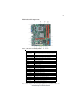
5 Motherboard Components Table of Motherboard Components LABEL COMPONENTS LGA775 socket for Intel® CoreTM 2 Quad/CoreTM 1. CPU Socket 2 Duo/Pentium® Dual-core/Celeron® processors 2. CPU_FAN CPU cooling fan connector 3. DDR2_1~2 240-pin DDR2 SDRAM slots 4. ATX_POWER Standard 24-pin ATX power connector 5. SATA1~4 Serial ATA connectors 6. IDE Primary IDE channel 7. F_PANEL Front panel switch/LED header 8. SYS_FAN System cooling fan connector 9. SPK Speaker header 10. CLR_CMOS Clear CMOS jumper 11.
6 Memo Introducing the Motherboard
7 Chapter 2 Installing the Motherboard Safety Precautions • • • • • Follow these safety precautions when installing the motherboard Wear a grounding strap attached to a grounded device to avoid damage from static electricity Discharge static electricity by touching the metal case of a safely grounded object before working on the motherboard Leave components in the static-proof bags they came in Hold all circuit boards by the edges.
8 Do not over-tighten the screws as this can stress the motherboard. Checking Jumper Settings This section explains how to set jumpers for correct configuration of the motherboard. Setting Jumpers Use the motherboard jumpers to set system configuration options. Jumpers with more than one pin are numbered. When setting the jumpers, ensure that the jumper caps are placed on the correct pins. The illustrations show a 2-pin jumper. When the jumper cap is placed on both pins, the jumper is SHORT.
9 Checking Jumper Settings The following illustration shows the location of the motherboard jumpers. Pin 1 is labeled. Jumper Settings Jumper Type Description Setting (default) 1-2: NORMAL CLR_CMOS 3-pin USBPWR_F 3-pin USBPWR_R 3-pin Clear CMOS 2-3: CLEAR Before clearing the CMOS, make sure to turn off the system. Front Panel USB Power Select Jumper 1-2: VCC 2-3: 5VSB Rear USB PS/2 Power Select Jumper 1-2: VCC 2-3: 5VSB 1 CLR_CMOS 1 USBPWR_F 1 USBPWR_R 1.
10 Installing Hardware Installing the Processor Caution: When installing a CPU heatsink and cooling fan make sure that you DO NOT scratch the motherboard or any of the surfacemount resistors with the clip of the cooling fan. If the clip of the cooling fan scrapes across the motherboard, you may cause serious damage to the motherboard or its components. On most motherboards, there are small surface-mount resistors near the processor socket, which may be damaged if the cooling fan is carelessly installed.
11 CPU Installation Procedure The following illustration shows CPU installation components. A. Read and follow the instructions shown on the sticker on the CPU cap. B. Unload the cap · Use thumb & forefinger to hold the lifting tab of the cap. · Lift the cap up and remove the cap completely from the socket. C. Open the load plate · Use thumb & forefinger to hold the hook of the lever, pushing down and pulling aside unlock it. · Lift up the lever. · Use thumb to open the load plate.
12 Installing Memory Modules This motherboard accommodates two memory modules. It can support two 240-pin DDR2 800/667. The total memory capacity is 8 GB. DDR2 SDRAM memory module table Memory module DDR2 667 DDR2 800 Memory Bus 333 MHz 400 MHz You must install at least one module in any of the two slots. Each module can be installed with 4 GB of memory; total memory capacity is 8 GB. Do not remove any memory module from its antistatic packaging until you are ready to install it on the motherboard.
13 Table A: DDR2 (memory module) QVL (Qualified Vendor List) The following DDR2 800/667 memory modules have been tested and qualified for use with this motherboard. Type Size 512 MB Vendor Module Nam e Apacer 78.91G92.9K5 Micron MT4HTF6464AY-667E1 PSC AL6E8E63J-6E1 Ramxel RML1520M38D6F-667 Samsung K4T51083QC AU01GE667C5KBGC Apacer 78.01G90.
14 Type Size 512 MB Vendor Module Nam e Infineon HYS64T64020HU-2.5-A Kingston KVR800D2N5/512 Micron MT8HTF6464AY-80ED4 Qimonda HYS72T64000HU-2.5-B A-DATA M2GVD6G3I41P0U1E5E Aeneon Apacer 1 GB AET760UD00-30DB97X AET760UD00-25DC08X AU01GE800C5KBGC 78.01GA0.
15 Expansion Slots Installing Add-on Cards The slots on this motherboard are designed to hold expansion cards and connect them to the system bus. Expansion slots are a means of adding or enhancing the motherboard’s features and capabilities. With these efficient facilities, you can increase the motherboard’s capabilities by adding hardware that performs tasks that are not part of the basic system.
16 Follow these instructions to install an add-on card: 1 2 3 Remove a blanking plate from the system case corresponding to the slot you are going to use. Install the edge connector of the add-on card into the expansion slot. Ensure that the edge connector is correctly seated in the slot. Secure the metal bracket of the card to the system case with a screw. 1.
17 Connecting Optional Devices Refer to the following for information on connecting the motherboard’s optional devices: SATA1~4: Serial ATA connectors These connectors are used to support the new Serial ATA devices for the highest data transfer rates (3.0 Gb/s), simpler disk drive cabling and easier PC assembly. It eliminates limitations of the current Parallel ATA interface. But maintains register compatibility and software compatibility with Parallel ATA.
18 F_USB1~2: Front Panel USB headers The motherboard has four USB ports installed on the rear edge I/O port array. Additionally, some computer cases have USB ports at the front of the case. If you have this kind of case, use auxiliary USB connector to connect the front-mounted ports to the motherboard.
19 LPT_H: Onboard parallel port header This is a header that can be used to connect to the printer, scanner or other devices.
20 IDE devices enclose jumpers or switches used to set the IDE device as MASTER or SLAVE. Refer to the IDE device user’s manual. Installing two IDE devices on one cable, ensure that one device is set to MASTER and the other device is set to SLAVE. The documentation of your IDE device explains how to do this. About SATA Connectors Your motherboard features four SATA connectors supporting a total of four drives.
21 Connecting I/O Devices The backplane of the motherboard has the following I/O ports: PS2 Mouse Use the upper PS/2 port to connect a PS/2 pointing device. PS2 Keyboard Use the lower PS/2 port to connect a PS/2 keyboard. Serial Port (COM) Use the COM port to connect serial devices such as mice or fax/modems. VGA Port Connect your monitor to the VGA port. LAN Port Connect an RJ-45 jack to the LAN port to connect your computer to the Network. USB Ports Use the USB ports to connect USB devices.
22 Connecting Case Components After you have installed the motherboard into a case, you can begin connecting the motherboard components. Refer to the following: 1 2 3 4 5 6 Connect the CPU cooling fan cable to CPU_FAN. Connect the standard power supply connector to ATX_POWER. Connect the case switches and indicator LEDs to the F_PANEL. Connect the system cooling fan connector to SYS_FAN. Connect the case speaker cable to SPK. Connect the auxiliary case power supply connector to ATX12V. 1.
23 CPU_FAN: CPU Cooling FAN Power Connector Pin 1 2 3 4 Signal Name Function GND System Ground +12V Power +12V Sense Sensor PWM PWM Users please note that the fan connector supports the CPU cooling fan of 1.1A ~ 2.2A (26.4W max) at +12V. ATX_POWER: ATX 24-pin Power Connector Pin 1 2 3 4 5 6 7 8 9 Signal Name Pin Signal Name 13 14 15 16 17 18 19 20 21 +3.3V +3.3V Ground +5V Ground +5V Ground PWRGD +5VSB +3.
24 ATX12V: ATX 12V Power Connector Pin 1 2 3 4 Signal Name Ground Ground +12V +12V Installing the Motherboard
25 Front Panel Header The front panel header (F_PANEL) provides a standard set of switch and LED headers commonly found on ATX or micro-ATX cases.
26 Memo Installing the Motherboard
27 Chapter 3 Using BIOS About the Setup Utility The computer uses the latest “American Megatrends Inc. ” BIOS with support for Windows Plug and Play. The CMOS chip on the motherboard contains the ROM setup instructions for configuring the motherboard BIOS. The BIOS (Basic Input and Output System) Setup Utility displays the system’s configuration status and provides you with options to set system parameters.
28 Press the delete key to access the BIOS Setup Utility. CMOS Setup Utility - Copyright (C) 1985-2005, American Megatrends, Inc.
29 Using BIOS When you start the Setup Utility, the main menu appears. The main menu of the Setup Utility displays a list of the options that are available. A highlight indicates which option is currently selected. Use the cursor arrow keys to move the highlight to other options. When an option is highlighted, execute the option by pressing . Some options lead to pop-up dialog boxes that prompt you to verify that you wish to execute that option.
30 For the purpose of better product maintenance, we reserve the right to change the BIOS items presented in the manual. The BIOS setup screens shown in this chapter are for reference only. Please visit our website for updated manual. Standard CMOS Setup This option displays basic information about your system. CMOS Setup Utility - Copyright (C) 1985-2005, American Megatrends, Inc.
31 f Primary IDE Master/Slave; SATA1~4 Your computer has one IDE channel and each channel can be installed with one or two devices (Master and Slave). In addition, this motherboard supports four SATA channels and each channel allows one SATA device to be installed. Use these items to configure each device on the SATA channel. CMOS Setup Utility - Copyright (C) 1985-2005, American Megatrends, Inc.
32 Advanced Setup This page sets up more advanced information about your system. Handle this page with caution. Any changes can affect the operation of your computer. CMOS Setup Utility - Copyright (C) 1985-2005, American Megatrends, Inc.
33 Boot Up Numlock Status (On) This item defines if the keyboard Num Lock key is active when your system is started. APIC Mode (Enabled) This item allows you to enable or disable the APIC (Advanced Programmable Interrupt Controller) mode. APIC provides symmetric multi-processing (SMP) for systems, allowing support for up to 60 processors. 1st/2nd/3rd Boot Device (Hard Disk Drive/CD/DVD/Removable Dev.
34 ECS eJIFFY Function (Disabled) Use this item to enable or disable the ECS eJIFFY Function. eJIFFY is ECS unique software program for the quick access to the internet without entering O.S. Please refer to Chapter 5 to know more about eJIFFY. Press to return to the main menu setting page. Advanced Chipset Setup This page sets up more advanced information about your system. Handle this page with caution. Any changes can affect the operation of your computer.
35 Integrated Peripherals This page sets up some parameters for peripheral devices connected to the system. CMOS Setup Utility - Copyright (C) 1985-2005, American Megatrends, Inc.
36 Parallel Port IRQ (IRQ7) Use this item to assign IRQ to the parallel port. USB Functions (Enabled) Use this item to enable or disable the USB function. Legacy USB Support (Enabled) Use this item to enable or disable support for legacy USB devices. Press to return to the main menu setting page. Power Management Setup This page sets up some parameters for system power management operation. CMOS Setup Utility - Copyright (C) 1985-2005, American Megatrends, Inc.
37 Resume By RING (Disabled) An input signal on the serial Ring Indicator (RI) line (in other words, an incoming call on the modem) awakens the system from a soft off state. Resume By PCI/PCI-E/Lan PME (Disabled) These items specify whether the system will be awakened from power saving modes when activity or input signal of the specified hardware peripheral or component is detected. Resume By USB (S3) (Disabled) This item allows you to enable/disable the USB device wakeup function from S3/S4 mode.
38 PCI/PnP Setup This page sets up some parameters for devices installed on the PCI bus and those utilizing the system plug and play capability. CMOS Setup Utility - Copyright (C) 1985-2005, American Megatrends, Inc. PCI/PnP Setup Init Display First PCI Help Item Select which graphics controller to use as the primary boot device.
39 f Smart Fan Function (Press Enter) Scroll to this item and press to view the following screen: CMOS Setup Utility - Copyright (C) 1985-2005, American Megatrends, Inc. Smart Fan Function Help Item Smart Fan Control SMART Fan Mode SMART Fan start PWM value CPU DeltaT SMART Fan start Offset (-) Fan1 Slope PWM value/1 UnitI Fan1 Full Speed Offset (-) Enabled Normal 28 +3 32 4 7 Options Normal: auto adjusts depending on the CPU temperature.
40 CMOS Setup Utility - Copyright (C) 1985-2005, American Megatrends, Inc. Smart Fan Function SMART Fan Function Smart Fan Mode SMART Fan start PWM value CPU DeltaT1 SMART Fan start TEMP. (°C) SMART Fan Slope PWM value CPU FAN Full Limit Temp Enabled Quiet 20 +3 68 14 PWM value/°C 75° C Help Item Options Normal: auto adjusts depending on the CPU temperature. Quiet: auto minimizes fan speed for quiet environment operation. Silent: auto restricts fan speed to make system more quietly.
41 CMOS Setup Utility - Copyright (C) 1985-2005, American Megatrends, Inc. Smart Fan Function Help Item SMART Fan Function Smart Fan Mode SMART Fan start PWM value CPU DeltaT1 SMART Fan start TEMP. (°C) SMART Fan Slope PWM value CPU FAN Full Limit Temp Enabled Manual 5 +3 70 12 PWM value/°C 80° C Options Normal: auto adjusts depending on the CPU temperature. Quiet: auto minimizes fan speed for quiet environment operation. Silent: auto restricts fan speed to make system more quietly.
42 ECS supports the latest PECI host technology. While using CoreTM 2 Quad or CoreTM 2 Duo CPU which supports PECI, the original images of the BIOS item “PC Health Status” and “Smart FAN Function” will be replaced by PECI mode and negative number. (The max data from PECI is zero.) CMOS Setup Utility - Copyright (C) 1985-2005, American Megatrends, Inc. PC Health Status Help Item -=- System Hardware Monitor-=Press Enter CPU Fan Speed : 2509 RPM : 1.088 V CPU Vcore VDIMM : 1.
43 Shutdown Temperature (Disabled) Enable you to set the maximum temperature the system can reach before powering down. System Component Characteristics These items display the monitoring of the overall inboard hardware health events, such as System & CPU temperature, CPU & DIMM voltage, CPU & system fan speed,...etc. • • • • CPU Temperature CPU Fan Speed CPU Vcore VDIMM Press to return to the main menu setting page.
44 Spread Spectrum (Enabled) If you enable spread spectrum, it can significantly reduce the EMI (Electro-Magnetic Interference) generated by the system. Press to return to the main menu setting page. Load Default Settings This option opens a dialog box that lets you install stability-oriented defaults for all appropriate items in the Setup Utility. Select and then press to install the defaults. Select and then press to not install the defaults.
45 User Password This page helps you install or change a password. CMOS Setup Utility - Copyright (C) 1985-2005, American Megatrends, Inc. User Password User Password : Not Installed mnlk : Move Enter : Select F1: General Help Help Item +/-/: Value F10: Save ESC: Exit F9: Load Default Settings User Password (Not Installed) This item indicates whether a user password has been set. If the password has been installed, Installed displays. If not, Not Installed displays.
46 Updating the BIOS You can download and install updated BIOS for this motherboard from the manufacturer’s Web site. New BIOS provides support for new peripherals, improvements in performance, or fixes for known bugs. Install new BIOS as follows: 1 If your motherboard has a BIOS protection jumper, change the setting to allow BIOS flashing. 2 If your motherboard has an item called Firmware Write Protect in Advanced BIOS features, disable it. (Firmware Write Protect prevents BIOS from being overwritten.
47 Chapter 4 Using the Motherboard Software About the Software DVD-ROM/CD-ROM The support software DVD-ROM/CD-ROM that is included in the motherboard package contains all the drivers and utility programs needed to properly run the bundled products. Below you can find a brief description of each software program, and the location for your motherboard version. More information on some programs is available in a README file, located in the same directory as the software.
48 Drivers Tab Setup Click the Setup button to run the software installation program. Select from the menu which software you want to install. Browse CD The Browse CD button is the standard Windows command that allows you to open Windows Explorer and show the contents of the support disk. Before installing the software from Windows Explorer, look for a file named README.TXT or something similar. This file may contain important information to help you install the software correctly.
49 2. Click Next. The following screen appears: 3. Check the box next to the items you want to install. The default options are recommended. 4. Click Next run the Installation Wizard. An item installation screen appears: 5. Follow the instructions on the screen to install the items. Drivers and software are automatically installed in sequence. Follow the onscreen instructions, confirm commands and allow the computer to restart a few times to complete the installation.
50 Windows Vista/7 will appear below UAC (User Account Control) message after the system restart. You must select “Allow” to install the next driver. Continue this process to complete the drivers installation. Manual Installation Insert the disk in the DVD-ROM/CD-ROM drive and locate the PATH.DOC file in the root directory. This file contains the information needed to locate the drivers for your motherboard.
51 Chapter 5 Setting Up eJIFFY Introduction eJIFFY is a fast boot program under Linux. Instead of waiting Windows O.S to start execution, eJIFFY is ready to provide users the instant enjoyment on web browsing, photo review and online chat just within several seconds after boot up. Note: eJIFFY is ECS optional feature utility corresponding to the DVD activation and BIOS setup. Please check the hard copy user’s guide or product color-box to see if the model has embodded eJIFFY feature.
52 Installation and BIOS Setup DVD Activation Finish the DVD utility setup, and then set the BIOS to complete eJIFFY activation. 1. Insert ECS software utility DVD and enter below “Utilities” screen. Click eJIFFY feature item to install. 2. Follow the onscreen instructions to finish eJIFFY setup.
53 3. After setting up eJIFFY under Windows, you can switch eJIFFY display/keyboard language from English to your local language. The changes will be applied after rebooting. Note: The keyboard language selection list offers several more regional keyboard setups to switch with the default English typing. Please refer to the usage FAQ for more tips.
54 4. Restart your computer after eJIFFY installation. Press or click the BIOS Setup button on the post screen to enter the BIOS setup page after boot up. 5. And then enter the Advanced Setup page to enable the item ECS eJIFFY Function. Press F10 to save the configuration and exit. Restart your computer. Note: 1. eJIFFY is available in SATA/IDE/AHCI mode. It does not support RAID configuration and the onboard 34-pin floppy drives. 2. Please refer to ECS website for new eJIFFY application updates.
55 Entering eJIFFY The post screen appears within several seconds after boot up and it has three buttons on it, Operating system, eJIFFY and BIOS Setup. Click to enter the normal OS you have installed such as Windows. Click to enter eJIFFY OS. Click to set the BIOS. If you click eJIFFY, the following screen will appear. And If you make no choice it will enter the normal OS automatically after ten seconds.
56 Feature Icons The following illustration shows the main feature icons that eJIFFY provides on the menu. eWeb: Firefox for web browsing/webmail and watching flash video. ePix: Photo viewing. ePal: On-line chat tool to use the most popular IMs in the world. (MSN, ICQ , AIM, etc.) Shows ePal on-line connection status. Shut Down/Restart: Ends your session and turns off the computer./Ends your session and restart the computer.. Click once to connect the storage disk to your computer.
57 Usage FAQ Language Control Panel: Besides setting English as the default interface, eJIFFY offers multi-language displays and keyboard settings for languageswitch. Open the language control panel to select a preferable language setting. Keyboard Language Setup Step1. Click to open the language control panel. Step 2: Click “Keyboard Language” icon to open the keyboard selection list, which offers several regional keyboard settings besides default English keyboard.
58 Click to enable all possible language inputs you want to apply, and click “Apply”: Move your mouse pointer on the text box and press Ctrl+Space. The language bar will then appear as follows. Click the language bar here.
59 How to change display language? Open the Language Control Panel and click to show the display language list. Check your desired display language. Your selected display language will be applied after rebooting. Note: Details about eJIFFY please refer to eJIFFY in disk.
60 Memo Setting Up eJIFFY
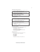
61 Chapter 6 Trouble Shooting Start up problems during assembly After assembling the PC for the first time you may experience some start up problems. Before calling for technical support or returning for warranty, this chapter may help to address some of the common questions using some basic troubleshooting tips. a) System does not power up and the fans are not running. 1.Disassemble the PC to remove the VGA adaptor card, DDR memory, LAN, USB and other peripherals including keyboard and mouse.
62 c) The PC suddenly shuts down while booting up. 1. The CPU may experience overheating so it will shutdown to protect itself. Ensure the CPU fan is working properly. 2. From the BIOS setting, try to disable the Smartfan function to let the fan run at default speed. Doing a Load Optimised Default will also disable the Smartfan. Start up problems after prolong use After a prolong period of use your PC may experience start up problems again.
If fail, contact RMA CLR CMOS and restart. Yes Halt at POST screen? Yes Check if monitor has display Yes Check if Power Supply Unit (PSU) is working Power Bu on is pressed but PC fails to start. CMOS setup error, - need to CLRCMOS. HDD problem.
64 Memo Trouble Shooting