Preface Copyright This publication, including all photographs, illustrations and software, is protected under international copyright laws, with all rights reserved. Neither this manual, nor any of the material contained herein, may be reproduced without written consent of the author. Version 1.0A Disclaimer The information in this document is subject to change without notice.
Declaration of Conformity This device complies with part 15 of the FCC rules. Operation is subject to the following conditions: • This device may not cause harmful interference. • This device must accept any interference received, including interference that may cause undesired operation.
TABLE OF CONTENTS Preface i Chapter 1 1 Introducing the Motherboard 1 Introduction...........................................................................................1 Pakage Contents..................................................................................1 Specifications......................................................................................2 Motherboard Components................................................................4 I/O Ports...................................
Chapter 4 53 Using the Motherboard Software 53 Auto-installing under Windows XP/Vista/7.................................53 Running Setup........................................................................53 Manual Installation..........................................................................55 ECS Utility Software (Intelligent EZ Utility).....................................55 Chapter 5 57 Trouble Shooting 57 Start up problems during assembly..............................................
Introduction Chapter 1 Chapter 1 Introducing the Motherboard Thank you for choosing the CDC-TI motherboard of high performance, enhanced function. This motherboard has Onboard Cedarview CPU with a Thin Mini-ITX form factor of 170 x 170 mm. This motherboard is based on Intel® NM10 Express Chipset. It supports up to 4 GB of system memory with single channel DDR3 SO-DIMM 1066/800 MHz. One optional PCI Express x1 slot is supported.
Chapter 1 Specifications CPU • • Intel® Onboard Cedarview CPU Intel FMB 10W Note: Please go to ECS website for the latest CPU support list. Chipset • Intel® NM10 Chipset Memory • • • Singel channel DDR3 SO-DIMM memory architecture 2 x 204-pin DDR3 SO-DIMM sockets support up to 4 GB Supports DDR3 1066/800 MHz DDR3 SDRAM Note: Please go to ECS website for the latest Memory support list.
• AMI BIOS with 32Mb SPI Flash ROM - Supports ECS MIB III Utility a. CPU Voltage Adjustable b. Memory Voltage Adjustable c. IMC Voltage Adjustable - Supports Plug and Play, STR(S3)/STD(S4), Multi Boot - Supports Hardware Monitor - Supports ACPI 3.
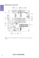
Chapter 1 Motherboard Components This picture may be different due to Optional Features on speccifications.
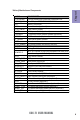
LABEL 1. CPU Socket 2. DIMM_1~2 3. BT 4. SPK 5. CLR_CMOS 6. PCIE 7. SPEAKER 8. SPDIFO 9. F_AUDIO 10. CIR 11. SPI_DEBUG 12. CASE 13.
Chapter 1 I/O Ports 1. DC-IN Port Connect the DC-IN port to the power adapter. 2. VGA Port Connect your monitor to the VGA port. 3. USB 2.0 Ports Use the USB 2.0 ports to connect USB 2.0 devices. 4. HDMI Port You can connect the display device to the HDMI port. 5. LAN Port Connect an RJ-45 jack to the LAN port to connect your computer to the Network. Link LED LAN LED Activity LED Link LED Status Description OFF Orange blinking OFF Green No data Active No link Link Activity LED LAN Port 6.
Chapter 2 Installing the Motherboard Follow these safety precautions when installing the motherboard: • • • • Wear a grounding strap attached to a grounded device to avoid damage from static electricity. Discharge static electricity by touching the metal case of a safely grounded object before working on the motherboard. Leave components in the static-proof bags.
2-3. Checking Jumper Settings This section explains how to set jumpers for correct configuration of the motherboard. Chapter 2 1. LCD_SEL: LCD select jumper (optional) 1.When your panel connects to LVDS, please check LCD Select header setting first. 2.Due to the differences of the panel parameters, please follow the above illustration to place the jumper caps.
2. CLR_CMOS: Clear CMOS jumper Chapter 2 The following illustration shows the location of the motherboard jumpers. Pin 1 is labeled. To avoid the system instability after clearing CMOS, we recommend users to enter the main BIOS setting page to “Load Default Settings” and then “Save and Exit Setup”.
2-4. Installing Hardware 2-4-1. Installing Memory Modules • • Chapter 2 • • This motherboard accommodates two memory modules. It can support two 204-pin DDR3 SO-DIMM 1066/800. Do not remove any memory module from its antistatic packaging until you are ready to install it on the motherboard. Handle the modules only by their edges. Do not touch the components or metal parts. Always wear a grounding strap when you handle the modules. You must install one module in DIMM1 or two modules in the two slots.
2-4-2. Installing Add-on Cards Chapter 2 The slots on this motherboard are designed to hold expansion cards and connect them to the system bus. Expansion slots are a means of adding or enhancing the motherboard’s features and capabilities. With these efficient facilities, you can increase the motherboard’s capabilities by adding hardware that performs tasks that are not part of the basic system. PCIE Slot The PCI Express x1 slot is fully compliant to the PCI Express Base Specification revision 2.0.
Follow these instructions to install an add-on card: Chapter 2 1 Remove a blanking plate from the system case corresponding to the slot you are going to use. 2 Install the edge connector of the add-on card into the expansion slot. Ensure that the edge connector is correctly seated in the slot. 3 Secure the metal bracket of the card to the system case with a screw. 1.
1 2 3 Remove a blanking plate from the system case, and insert the wireless card into the MINIPCIE slot rightwards, then tighten the two screws (Please refer to Picture 1). Press the metal connector of the cable into the connector on the wireless card. Ensure that the metal connector is correctly seated (Please refer to Picture 2).
2-4-3. Connecting Optional Devices Refer to the following for information on connecting the motherboard’s optional devices: Chapter 2 14 No. Components No.
1. SATA1~2: Serial ATA connectors Chapter 2 SATA1~2 connectors are used to support the Serial ATA 3.0Gb/s device, simpler disk drive cabling and easier PC assembly. It eliminates limitations of the current Parallel ATA interface. But maintains register compatibility and software compatibility with Parallel ATA. 2. TOUCH/CAMERA/CR: Touch board header/CCD Header/Card reader header Users please note to install the card to the correct header.
3. COM: Onboard serial port header (optional) Connect a serial port extension bracket to this header to add a serial port to your system. Chapter 2 4. LPT: Onboard parallel port Header (optional) This is a header that can be used to connect to the printer, scanner or other devices.
Chapter 2 5. DLVDS: Dual Channels LVDS interface (optional) 1. You can connect the large end of the cable to the LED Panel, and connect the other small end to the slot on the motherboard. 2.Due to the chipset limitation, using dual displays LVDS(AIO) + VGA or LVDS(AIO) + HDMI will cause the problem that you may not enter BIOS setup or have the display problem. 6.
7. BKLT_CTRL: LCD panel Backlight control (optional) Chapter 2 8.
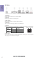
Chapter 2 9. SPEAKER: 2 Channels audio speaker header (optional) 10. F_AUDIO: Front Panel Audio Header The front panel audio header allows the user to install auxiliary front-oriented microphone and line-out ports for easier access. This header supports HD audio by default. If you want connect an AC’ 97 front panel audio to HD onboard headers, please set as below picture.
AC’ 97 Audio Configuration: To enable the front panel audio connector to support AC97 Audio mode. If you use AC’ 97 Front Panel, please tick off the option of “ Disabled Front Panel Detect ”. If you use HD Audio Front Panel, please don’ t tick off “Disabled Front Panel Detect ” . Chapter 2 * For reference only If you use AC’ 97 Front Panel, please don’ t tick off “Using Front Jack Detect ”. If you use HD Audio Front Panel, please tick off the option of “Using Front Jack Detect ”.
11. SPDIFO: SPDIF out header (optional) Chapter 2 This is an optional header that provides an SPDIFO (Sony/Philips Digital Interface) output to digital multimedia device through optical fiber or coaxial connector. 12. CASE: Chassis Intrusion Detect Header This detects if the chassis cover has been removed. This function needs a chassis equipped with instrusion detection switch and needs to be enabled in BIOS.
13. LDC: Debug Card Header Chapter 2 14. F_USB: Front Panel USB 2.0 header The motherboard has one USB 2.0 headers supporting two USB 2.0 ports. Additionally, some computer cases have USB ports at the front of the case. If you have this kind of case, use auxiliary USB connector to connect the front-mounted ports to the motherboard. Please make sure that the USB cable has the same pin assignment as indicated above. A different pin assignment may cause damage or system hangup.
2-4-4. Installing a Hard Disk Drive/Optical Disk Drive/SATA Hard Drive This section describes how to install a Hard Disk Drive/Optical Disk Drive/SATA Hard Drive. Your motherboard features two SATA connectors supporting a total of two drives. SATA refers to Serial ATA (Advanced Technology Attachment) is the standard interface for the IDE hard drives which are currently used in most PCs. These connectors are well designed and will only fit in one orientation.
2-4-5. Connecting Case Components After you have installed the motherboard into a case, you can begin connecting the motherboard components. Refer to the following: Chapter 2 No. Components No. Components 1 HDD_PWR/ODD_PWR 3 SYS_FAN1~2 2 PANEL 4 SPK 1.
2. Panel Header Chapter 2 The front panel header (PANEL) provides a standard set of switch and LED headers commonly found on ATX or Micro ATX cases. Refer to the table below for information: Hard Drive Activity LED Connecting pins 1 and 3 to a front panel mounted LED provides visual indication that data is being read from or written to the hard drive. For the LED to function properly, an IDE drive should be connected to the onboard IDE interface.
3. SYS_FAN1~2: System Cooling FAN Power Connectors Connect the system cooling fan connector to SYS_FAN. Chapter 2 Users please note that the fan connector supports the CPU cooling fan of 1.1A ~ 2.2A (26.4W max) at +12V. 4. SPK: Buzzer Header (optional) Connect the case speaker cable to SPK. This concludes Chapter 2. The next chapter covers the BIOS.
Chapter 3 Using BIOS About the Setup Utility The BIOS (Basic Input and Output System) Setup Utility displays the system’s configuration status and provides you with options to set system parameters. The parameters are stored in battery-backed-up CMOS RAM that saves this information when the power is turned off. When the system is turned back on, the system is configured with the values you stored in CMOS.
Press the delete key to access BIOS Setup Utility. Chapter 3 Resetting the Default CMOS Values When powering on for the first time, the POST screen may show a “CMOS Settings Wrong” message. This standard message will appear following a clear CMOS data at factory by the manufacturer. You simply need to Load Default Settings to reset the default CMOS values. Note: Changes to system hardware such as different CPU, memories, etc. may also trigger this message.
In this manual, default values are enclosed in parenthesis. Submenu items are denoted by a icon. The default BIOS setting for this motherboard apply for most conditions with optimum performance. We do not suggest users change the default values in the BIOS setup and take no responsibility to any damage caused by changing the BIOS settings. BIOS Navigation Keys The BIOS navigation keys are listed below: KEY FUNCTION Exits the current menu mnlk Scrolls through the items on a menu +/- Change Opt.
Main Menu This menu shows the information of BIOS and enables you to set the system language, date and time. Main Advanced Chipset Tweak Boot System Date System Time Exit Choose the system default language BIOS Information System Language Security English Wed 02/01/2012 20:34:31 Chapter 3 lk : Select Screen mn /Click: Select Item Enter/Dbl Click : Select +/- : Change Opt.
Advanced Menu The Advanced menu items allow you to change the settings for the CPU and other system. Advanced Chipset Legacy OpROM Support Launch PXE OpROM Launch Storage OpROM Tweak Boot Disabled Enabled Power Management Setup LAN Configuration PC Health Status ACPI Settings CPU Configuration SATA Configuration USB Configuration Super IO Configuration Security Exit Enable/Disable Onboard LAN Option ROM lk : Select Screen mn /Click: Select Item Enter/Dbl Click : Select +/- : Change Opt.
Power Management Setup This page sets up some parameters for system power management operation. Main Advanced Chipset Tweak Boot Resume By RING Resume By PME Resume By USB (S3) EUP Function Power LED Type Security Exit About Resume by Ring Power Management Setup Disabled Disabled Disabled Enabled Dual Color LED lk : Select Screen mn /Click: Select Item Chapter 3 Enter/Dbl Click : Select +/- : Change Opt.
LAN Configuration The item in the menu shows the LAN-related information that the BIOS automatically detects. Main Advanced Chipset Tweak Boot LAN Configuration Onboard LAN Controller Security Exit Enabled/Disabled Onboard LAN 1 Controller Enabled lk : Select Screen Enter/Dbl Click : Select +/- : Change Opt.
PC Health Status On motherboards support hardware monitoring, this item lets you monitor the parameters for critical voltages, temperatures and fan speeds. Main Advanced Chipset Tweak Boot Security Exit PC Health Status Smart Fan Function Chapter 3 System Fan 1 Speed System Temperature System Fan 2 Speed CPU Voltage DIMM Voltage VAXG Voltage : : : : : 2518 RPM 39oC 0 RPM 1.188V 1.485V 1.001V : -=- PECI Mode -=Offset to TCC Activation Temp.
System Smart Fan 1/2 Control (Enabled) These items enable you to define the System by smartly adjusting the System Fans. When they are set at certain temperature, the System Fan PWM values will change accordingly. Smart Fan Mode (Normal) This item allows you to select the fan mode (Normal, Quiet, Silent, or Manual) for a better operation environment. If you choose Normal mode, the fan speed will be auto adjusted depending on the CPU temperature.
ACPI Configuration The item in the menu shows the highest ACPI sleep state when the system enters suspend. Main Advanced Chipset Tweak Boot ACPI Settings ACPI Sleep State S3 (Suspend to RAM) Security Exit Select the highest ACPI sleep state the system will enter when the SUSPEND button is pressed. lk : Select Screen Chapter 3 mn /Click: Select Item Enter/Dbl Click : Select +/- : Change Opt.
CPU Configuration The item in the menu shows the CPU. Advanced Chipset Tweak Boot Intel(R) Atom (TM) CPU D2700 EMT64 Processor Speed Processor Stepping Microcode Revision Processor Cores Intel HT Technology Hyper-threading Limit CPUID Maximum Execute Disable Bit @ 2.
Excute Disable Bit (Enabled) This item allows the processor to classify areas in memory by where application code can execute and where it cannot. When a malicious worm attempts to insert code in the buffer, the processor disables code execution, preventing damage or worm propagation. Replacing older computers with Execute Disable Bit enabled systems can halt worm attacks, reducing the need for virus related repair. Press to return to the Advanced Menu page.
SATA Configuration Use this item to show the mode of serial SATA configuration options. Main Advanced Chipset Tweak Boot SATA Configuration SATA Mode Serial-ATA Controller SATA Port1 SATA Port2 Security Exit (1) IDE Mode. (2) AHCI Mode. IDE Mode Enhanced Not Present ST3500418AS (500.1G lk : Select Screen Enter/Dbl Click : Select +/- : Change Opt.
USB Configuration Use this item to show the information of USB configuration. Main Advanced Chipset Tweak Boot All USB Devices Legacy USB Support Security Exit Enabled/Disabled All USB Devices USB Configuration Enabled Enabled lk : Select Screen mn /Click: Select Item Chapter 3 Enter/Dbl Click : Select +/- : Change Opt. F1: General Help F2: Previous Values F3: Optimized Defaults F4: Save & Exit ESC/Right Click: Exit All USB Devices (Enabled) Use this item to enable or disable all USB devices.
Super IO Configuration Use this item to show the information of Super IO configuration. Main Advanced Chipset Tweak Boot Security Exit Set Parameters of Serial Port 0 (COMA) Super IO Configuration Serial Port 0 Configutation Parallel Port Configutation CIR Controller Configuration lk : Select Screen Enter/Dbl Click : Select +/- : Change Opt.
Parallel Port Configuration Scroll to this item and press to view the following screen: Main Advanced Chipset Tweak Boot Security Exit Enabled or Disabled Parallel Port (LPT/LPTE) Parallel Port Configuration Parallel Port Device Settings Enabled IO=378h; IRQ=5; Change Settings Device Mode Auto Standard Parallel P... lk : Select Screen mn /Click: Select Item Chapter 3 Enter/Dbl Click : Select +/- : Change Opt.
CIR Controller Configuration Scroll to this item and press to view the following screen: Main Advanced Chipset Tweak Boot Exit Enabled or Disabled CIR Controller CIR Controller Configuration CIR Controller Security Enabled lk : Select Screen Enter/Dbl Click : Select +/- : Change Opt.
Chipset Menu The chipset menu items allow you to change the settings for the North chipset, South chipset and other system. Main Advanced Chipset Tweak Boot North Bridge South Bridge Exit lk : Select Screen mn/Click: Select Item Enter/Dbl Click : Select +/- : Change Opt.
North Bridge Scroll to this item and press to view the following screen: Main Advanced Chipset Tweak Boot North Bridge DVMT Mode Select DVMT Memory DVMT Mode 128MB Security Exit DVMT Mode/Fixed Mode Select LCD Panel BOOTROM Protection Enabled lk : Select Screen mn /Click: Select Item Enter/Dbl Click : Select +/- : Change Opt.
South Bridge Scroll to this item and press to view the following screen: Main Advanced Chipset Tweak Boot South Bridge Restore AC Power Loss Power Off Audio Configuration Azalia HD Audio Enabled Case Open Warning Chassis Opened Disabled No Security Exit Specify what state to go to when power is re-applied after a power failure (G3 state). Chapter 3 lk : Select Screen mn /Click: Select Item Enter/Dbl Click : Select +/- : Change Opt.
Tweak Menu This page enables you to monitor or set some information of the processor you have installed in your system. Advanced Chipset Tweak Boot Enabled Enabled Intel(R) Atom(TM) CPU D2700 Processor Speed Total Memory @ 2.13GHZ 2132 MHZ 2048 MB Security Exit Enabled/Disable Spread Spectrum lk : Select Screen mn /Click: Select Item Enter/Dbl Click : Select +/- : Change Opt.
Warning: Over-clocking components can adversely affect the reliability of the system and introduce errors into your system. Over-clocking can permanently damage the motherboard by generating excess heat in components that are run beyond the rated limits. Fail-Safe Procedures for Over-clocking Chapter 3 48 When end-users encounter failure after attempting over-clocking, please take the following steps to recover from it. 1. Shut down the computer. 2.
Boot Menu This page enables you to set the keyboard NumLock state. Advanced Chipset Tweak Boot Boot Configuration Bootup NumLock State Set Boot Priority 1st Boot 2nd Boot 3rd Boot 4th Boot 5thBoot 6thBoot 7th Boot 8th Boot On Hard Disk: ST350041...
Security Menu This page enables you to set setup administrator password and user password. Main Advanced Chipset Tweak Boot Security Exit Set Setup Administrator Password Administrator Password Creat New Password Chapter 3 lk : Select Screen mn /Click: Select Item Enter/Dbl Click : Select +/- : Change Opt. F1: General Help F2: Previous Values F3: Optimized Defaults F4: Save & Exit ESC/Right Click: Exit Administrator Password Press to setup administrator password.
Exit Menu This page enables you to exit system setup after saving or without saving the changes. Main Advanced Chipset Tweak Boot Security Back to EZ Mode Exit Go back to EZ Mode. lk : Select Screen mn /Click: Select Item Enter/Dbl Click : Select +/- : Change Opt.
Boot Override Use this item to select the boot device. Updating the BIOS You can download and install updated BIOS for this motherboard from the manufacturer’s Website. New BIOS provides support for new peripherals, improvements in performance, or fixes for known bugs. Install new BIOS as follows: Chapter 3 1 If your motherboard has a BIOS protection jumper, change the setting to allow BIOS flashing. 2 If your motherboard has an item called Firmware Write Protect in Advanced BIOS features, disable it.
Chapter 4 Using the Motherboard Software Auto-installing under Windows XP/Vista/7 The auto-install DVD-ROM makes it easy for you to install the drivers and software. The support software DVD-ROM disc loads automatically under Windows XP/Vista/ 7. When you insert the DVD-ROM disc in the DVD-ROM drive, the auto-run feature will automatically bring up the installation screen. The screen has four buttons on it: Setup, Utilities, Browse CD and Exit. Click “Exit” button to close the Auto-Setup window.
Click Next. The following screen appears: 3. Check the box next to the items you want to install. The default options are recommended. 4. Click Next to run the Installation Wizard. An item installation screen appears: 5. Follow the instructions on the screen to install the items. Chapter 4 2. Drivers and software are automatically installed in sequence. Follow the onscreen instructions, confirm commands and allow the computer to restart a few times to complete the installation.
Manual Installation If the auto-install DVD-ROM does not work on your system, you can still install drivers through the file manager for your OS (for example, Windows Explorer). Look for the chipset and motherboard model, and then browse to the directory and path to begin installing the drivers. Most drivers have a setup program (SETUP.EXE) that automatically detects your operating system before installation. Other drivers have the setup program located in the operating system subfolder.
eBLU ECS eBLU utility makes BIOS update faster and easier. eBLU will list the latest BIOS with a default check-mark. Click”install” button to install.
Chapter 5 Trouble Shooting Start up problems during assembly After assembling the PC for the first time you may experience some start up problems. Before calling for technical support or returning for warranty, this chapter may help to address some of the common questions using some basic troubleshooting tips. You may also log onto our ECS website for more information: http:// www.ecs.com.tw/ECSWebSite/Support/Support_FAQ.
2. From the BIOS setting, try to disable the Smartfan function to let the fan run at default speed. Doing a Load Optimised Default will also disable the Smartfan. Start up problems after prolong use After a prolong period of use your PC may experience start up problems again. This may be caused by breakdown of devices connected to the motherboard such as HDD, CPU fan, etc. The following tips may help to revive the PC or identify the cause of failure. 1. Clear the CMOS values using the CLR_CMOS jumper.
59 If fail, contact RMA CLR CMOS and restart. Yes Halt at POST screen Yes Check if monitor has display Yes Check if Power Supply Unit (PSU) is working Power Bu on is pressed but PC fails to start. - need to CLRCMOS. HDD problem.
Memo Chapter 5 60 CDC-TI USER MANUAL