iii
iv
Preface Copyright This publication, including all photographs, illustrations and software, is protected under international copyright laws, with all rights reserved. Neither this manual, nor any of the material contained herein, may be reproduced without written consent of the author. Version 3.0 Disclaimer The information in this document is subject to change without notice.
ii Declaration of Conformity This device complies with part 15 of the FCC rules. Operation is subject to the following conditions: • • This device may not cause harmful interference, and This device must accept any interference received, including interference that may cause undesired operation. Canadian Department of Communications This class B digital apparatus meets all requirements of the Canadian Interference-causing Equipment Regulations.
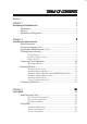
iii TABLE OF CONTENTS Preface i Chapter 1 1 Introducing the Motherboard 1 Introduction................................................................................................1 Features.......................................................................................................2 Motherboard Components.......................................................................4 Chapter 2 7 Installing the Motherboard 7 Safety Precautions.....................................................
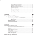
iv Power Management Setup Page..................................................31 PCI/Plug and Play Setup Page....................................................32 BIOS Security Features Setup Page.............................................33 CPU PnP Setup Page...................................................................33 Hardware Monitor Page..............................................................34 Load Optimal Defaults................................................................
1 Chapter 1 Introducing the Motherboard Introduction Thank you for choosing this motherboard. This motherboard is a high performance, enhanced function motherboard that supports Socket 754 AMD Sempron/Athlon 64 processors for high-end business or personal desktop markets. The motherboard incorporates the SiS761GX Northbridge (NB) and SiS964 Southbridge (SB) chipsets.
2 Feature Processor This motherboard uses a 754-pin socket that carries the following features: • Accommodates AMD Sempron/Athlon 64 processors • Supports up to 1600 MT/s HyperTransportTM (HT) interface speeds HyperTransportTM Technology is a point-to-point link between two devices, it enables integrated circuits to exchange information at much higher speeds than currently available interconnect technologies.
3 Expansion Options The motherboard comes with the following expansion options: • One PCI Express slot for Graphics interface • Three 32-bit PCI slots • Two IDE headers which support four IDE devices • One floppy disk drive interface • Two 7-pin SATA connectors • One Communications Networking Riser (CNR1) slot This motherboard supports Ultra DMA bus mastering with transfer rates of 133/100/66 MB/s.
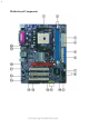
4 Motherboard Components Introducing the Motherboard
5 Table of Motherboard Components 1 2 3 4 5 6 7 8 9 10 11 12 LABEL CPU Socket DIMM1~2 FDD ATX_POWER IDE1 IDE2 SYS_FAN SATA1~SATA2 PANEL1 BIOS_WP USB3 ~ 4 CLR_CMOS COMPONENT Socket 754 for AMD K8 processor 184-pin DDR SDRAM slots Floppy disk drive connector Standard 24-pin ATX power connector Primary IDE connector Secondary IDE connector System cooling fan connector Serial ATA connectors Front Panel switch/LED header BIOS flash protect jumper Front Panel USB headers Clear CMOS jumper 13 14 15 16 17 18
6 Memo Introducing the Motherboard
7 Chapter 2 Installing the Motherboard Safety Precautions • • • • • Follow these safety precautions when installing the motherboard Wear a grounding strap attached to a grounded device to avoid damage from static electricity Discharge static electricity by touching the metal case of a safely grounded object before working on the motherboard Leave components in the static-proof bags they came in Hold all circuit boards by the edges.
8 Do not over-tighten the screws as this can stress the motherboard. Checking Jumper Settings This section explains how to set jumpers for correct configuration of the motherboard. Setting Jumpers Use the motherboard jumpers to set system configuration options. Jumpers with more than one pin are numbered. When setting the jumpers, ensure that the jumper caps are placed on the correct pins. The illustrations show a 2-pin jumper. When the jumper cap is placed on both pins, the jumper is SHORT.
9 Checking Jumper Settings The following illustration shows the location of the motherboard jumpers. Pin 1 is labeled. Jumper Settings Jumper Type Description CLR_CMOS 3-pin CLEAR CMOS Setting (default) 1-2: NORMAL 2-3: Clearing Before clearing the CMOS, make sure to turn the system off.
10 Connecting Case Components After you have installed the motherboard into a case, you can begin connecting the motherboard components. Refer to the following: 1 2 3 4 5 Connect the CPU cooling fan cable to CPU_FAN. Connect the system cooling fan connector to SYS_FAN Connect the case switches and indicator LEDs to the PANEL1. . Connect the standard power supply connector to ATX_POWER. Connect the auxiliary case power supply connector to ATX12V.
11 CPU_FAN/SYS_FAN: FAN Power Connectors Pin Signal Name Function 1 GND System Ground 2 3 +12V Power +12V Sensor Sense ATX_POWER: ATX 24-pin Power Connector Pin Signal Name 1 2 3 4 5 6 7 8 9 +3.3V 10 11 12 +12V +3.3V Ground +5V Ground +5V Ground PWRGD +5VSB +12V +3.3V Pin 13 14 15 16 17 18 19 20 21 22 23 24 Signal Name +3.
12 Front Panel Header The front panel header (PANEL1) provides a standard set of switch and LED headers commonly found on ATX or micro-ATX cases.
13 Installing Hardware Installing the Processor Caution: When installing a CPU heatsink and cooling fan make sure that you DO NOT scratch the motherboard or any of the surface-mount resistors with the clip of the cooling fan. If the clip of the cooling fan scrapes across the motherboard, you may cause serious damage to the motherboard or its components. On most motherboards, there are small surface-mount resistors near the processor socket, which may be damaged if the cooling fan is carelessly installed.
14 CPU Installation Procedure The following illustration shows CPU installation components. 1 2 3 4 5 Install your CPU. Pull up the lever away from the socket and lift up to 90-degree angle. Locate the CPU cut edge (the corner with the pin hold noticeably missing). Align and insert the CPU correctly. Press the lever down and apply thermal grease on top of the CPU. Put the CPU Fan down on the retention module and snap the four retention legs of the cooling fan into place.
15 Installing Memory Modules This motherboard accommodates two 184-pin unbuffered Double Data Rate (DDR) SDRAM (Synchronous Dynamic Random Access Memory) memory modules, and can support DDR400/DDR333/DDR266/DDR200 memory types. Each module can be installed with 1GB of memory, and its total maximum memory size is 2 GB.
16 Table A: Unbuffered DIMM Support for 754-pin 4.1.
17 Installing a Hard Disk Drive/CD-ROM/SATA Hard Drive This section describes how to install IDE devices such as a hard disk drive and a CD-ROM drive. About IDE Devices Your motherboard has a primary and secondary IDE channel interface (IDE1 and IDE2). An IDE ribbon cable supporting two IDE devices is bundled with the motherboard. You must orient the cable connector so that the pin1 (color) edge of the cable correspoinds to the pin 1 of the I/O port connector.
18 About SATA Connectors Your motherboard features two SATA connectors supporting a total of two drives. SATA refers to Serial ATA (Advanced Technology Attachment) is the standard interface for the IDE hard drives which are currently used in most PCs. These connectors are well designed and will only fit in one orientation. Locate the SATA connectors on the motherboard and follow the illustration below to install the SATA hard drives.
19 Installing a Floppy Diskette Drive The motherboard has a floppy diskette drive (FDD) interface and ships with a diskette drive ribbon cable that supports one or two floppy diskette drives. You can install a 5.25-inch drive and a 3.5-inch drive with various capacities. The floppy diskette drive cable has one type of connector for a 5.25-inch drive and another type of connector for a 3.5-inch drive.
20 PCIE1 slot The PCI Express x16 slot is fully compliant to the PCI Express Base Specification revision 1.0a as well PCI Slots This motherboard is equipped with three standard PCI slots. PCI stands for Peripheral Component Interconnect and is a bus standard for expansion cards, which for the most part, is a supplement of the older ISA bus standard. The PCI slots on this board are PCI v2.3 compliant. CNR1 Slot This slot is used to insert CNR cards with Modem and Audio functionality.
21 Connecting Optional Devices Refer to the following for information on connecting the motherboard’s optional devices: SPDIFO1: SPDIF out header This is an optional header that provides an S/PDIF (Sony/Philips Digital Interface) output to digital multimedia device through optical fiber or coaxial connector.
22 SATA1/SATA2: Serial ATA connectors These connectors are use to support the new Serial ATA devices for the highest date transfer rates (150 MB/s), simpler disk drive cabling and easier PC assembly. It eliminates limitations of the current Parallel ATA interface. But maintains register compatibility and software compatibility with Parallel ATA.
23 Connecting I/O Devices The backplane of the motherboard has the following I/O ports: PS2 Mouse Use the upper PS/2 port to connect a PS/2 pointing device. PS2 Keyboard Use the lower PS/2 port to connect a PS/2 keyboard. Parallel Port (LPT) Use LPT to connect printers or other parallel devices. Serial Port (COM1) Use the COM port to connect serial devices such as mice or fax/modems. COM1 is identified by the system as COM1/3. VGA Port Connect your monitor to the VGA port.
24 Memo Installing the Motherboard
25 Chapter 3 Using BIOS About the Setup Utility The computer uses the latest American Megatrends BIOS with support for Windows Plug and Play. The CMOS chip on the motherboard contains the ROM setup instructions for configuring the motherboard BIOS. The BIOS (Basic Input and Output System) Setup Utility displays the system’s configuration status and provides you with options to set system parameters.
26 Press DEL to enter SETUP Press the delete key to access the BIOS Setup Utility: CMOS Setup Utility -- Copyright (C) 1985-2003, American Megatrends, Inc.
27 Updating the BIOS You can download and install updated BIOS for this motherboard from the manufacturer’s Web site. New BIOS provides support for new peripherals, improvements in performance, or fixes for known bugs. Install new BIOS as follows: 1 If your motherboard has a BIOS protection jumper, change the setting to allow BIOS flashing. 2 If your motherboard has an item called Firmware Write Protect in Advanced BIOS features, disable it. (Firmware Write Protect prevents BIOS from being overwritten.
28 Standard CMOS Setup This option displays basic information about your system. CMOS SETUP UTILITY – Copyright (C) 1985-2003, American Megatrends, Inc. Standard CMOS Setup System Time System Date 00:01:25 Fri 09/13/2005 Primary IDE Master Primary IDE Slave Secondary IDE Master Secondary IDE Slave S-ATA 1 S-ATA 2 Hard Disk Not Detected CD/DVD ROM Not Detected Not Detected Not Detected Floppy A Floppy B 1.44 MB 3 1/2” Disabled Help Item User [Enter], [TAB] or [SHIFT-TAB] to select a field.
29 Advanced Setup Page This page sets up more advanced information about your system. Handle this page with caution. Any changes can affect the operation of your computer. CMOS SETUP UTILITY – Copyright (C) 1985-2003, American Megatrends, Inc.
30 Features Setup Page This page sets up some parameters for peripheral devices connected to the system. CMOS SETUP UTILITY – Copyright (C) 1985-2003, American Megatrends, Inc.
31 Onboard LAN Boot ROM (Disabled) Use this item to enable or disable the booting from the onboard LAN or a network add-in card with a remote boot ROM installed. OnBoard USB Function (Enabled) Enable this item if you plan to use the USB ports on this motherboard. USB Function For DOS (Disabled) Enable this item if you plan to use the USB ports on this motherboard in a DOS environment. Press to return to the main menu setting page.
32 Resume from USB Device (Disabled) This option allows the activity of the USB devices to wake up the system from S3 sleep state. ACPI Enhanced Efficiency (Disabled) This item allows you to enable or disable ACPI Enhanced Efficiency function. Press to return to the main menu setting page. PCI / Plug and Play Setup Page .This page sets up some parameters for devices installed on the PCI bus and those utilizing the system plug and play capability.
33 BIOS Security Features Setup Page This page helps you install or change a password. CMOS SETUP UTILITY – Copyright (C) 1985-2003, American Megatrends, Inc. BIOS Security Features Setup Security Settings Help Item Supervisor Password : Not Installed Change Supervisor Password Install or Change the password. Press Enter : Move Enter: Select +/-: Value F1: General Help F9: Optimized Defaults F10: Save ESC: Exit Supervisor Password This item indicates whether a supervisor password has been set.
34 Manufacturer These items show the brand of the CPU installed in your system. CPU Clock (200 MHz) This item allows you to adjust the CPU clock to 200MHz. You can key-in the numbers within the range to make a precise and ideal adjustment. DRAM Frequency (By SPD) This item shows the frequency of the DRAM in your system. Press to return to the main menu setting page. Hardware Monitor Page This page sets up some parameters for the hardware monitoring function of this motherboard.
35 Load Optimal Defaults This option opens a dialog box that lets you install optimized defaults for all appropriate items in the Setup Utility. Press and then to install the defaults. Press and then to not install the defaults. The optimized defaults place demands on the system that may be greater than the performance level of the components, such as the CPU and the memory.
36 Memo Using BIOS
37 Chapter 4 Using the Motherboard Software About the Software CD-ROM The support software CD-ROM that is included in the motherboard package contains all the drivers and utility programs needed to properly run the bundled products. Below you can find a brief description of each software program, and the location for your motherboard version. More information on some programs is available in a README file, located in the same directory as the software.
38 Setup Tab Setup Click the Setup button to run the software installation program. Select from the menu which software you want to install. Browse CD The Browse CD button is the standard Windows command that allows you to open Windows Explorer and show the contents of the support CD. Before installing the software from Windows Explorer, look for a file named README.TXT, INSTALL.TXT or something similar. This file may contain important information to help you install the software correctly.
39 2. Click Next. The following screen appears: 3. Check the box next to the items you want to install. The default options are recommended. 4. Click Next run the Installation Wizard. An item installation screen appears: 5. Follow the instructions on the screen to install the items. Drivers and software are automatically installed in sequence. Follow the onscreen instructions, confirm commands and allow the computer to restart a few times to complete the installation.
40 Manual Installation Insert the CD in the CD-ROM drive and locate the PATH.DOC file in the root directory. This file contains the information needed to locate the drivers for your motherboard. Look for the chipset and motherboard model; then browse to the directory and path to begin installing the drivers. Most drivers have a setup program (SETUP.EXE) that automatically detects your operating system before installation. Other drivers have the setup program located in the operating system subfolder.
41 Chapter 5 SiS 964 SATA RAID Setup Guide Introduction for SiS964 SATA RAID Function The 964 S-ATA controller only support two serial ATA on two independent ports. The Serial ATA RAID is designed to provide a cost-effective, high performance RAID solution that adds performance and/or reliability to PC desktops and/or servers using Serial ATA/150 hard disks. Serial ATA RAID function supports striping (RAID 0), mirroring (RAID 1), and span (JBOD).
42 4 JBOD: (Just a Bunch of Drives). Also known as “Spanning”. Two or more hard drives are required. Several hard disk types configured as a single hard disk. The hard drives are simply hooked up in series. This expands the capacity of your drive and results in a useable total capacity. However, JBOD will not increase any performance or data security. Installing Software Drivers SiS provides RAID driver for SiS 964 SATA with RAID function.
43 Confirming Windows 98/Me Driver Installation 1 2 3 From Windows 98/Me, open the Control Panel from “My Computer” followed by the System icon. Choose the “Device Manager” tab. Click the “+” in front of “IDE ATA/ATAPI Controllers” hardware type. The driver “SiS 180 IDE Dual Channel” and “SiS 180 IDE/RAID Controller” should appear. BIOS Utility Operation BIOS Utility supports windows 2000/XP/98/Me. Starting BIOS Utility 1 Boot your system.
44 Create RAID • SIS 964 controller support RAID 0, RAID 1 and JBOD. Creating a RAID 0 (Stripe) Array for Performance • SIS 180 enables users to create striped arrays with 2, 3, or 4 drives. • SIS 964 only supports 2 SATA drivers to create a stripe array. To create an array for best performance, follow these steps: 1 2 Press to start creating a RAID array. Press <2> and to select RAID 0. 3 You will have two selections to create a RAID 0 array. The default value is <1>.
45 5 Use <↑ > < ↓ > to select disk, and press to select disk, to exit. When you press on the disk you wanted, the RAID Type will be changed from Single to RAID 0. An the disk you select first will be the SOURCE disk. 6 Next, you will see a message “Split the SOURCE(DISK x) data to RAID disks?”. Press and to create RAID 0 array only or press and to split the data from source disk to other disks. 7 Starting splitting action, the following frame will be shown.
46 9 10 Press again to exit this BIOS utility and the red message frame will show. Press and to save changes. Once the array has been created, you will need to FDISK and format the array as if it were a new single hard drive. Creating a RAID 1 (Mirror) Array SIS 964/180 enables users to create Mirror arrays with 2 drives only. To create a Mirror array, follow these steps: 1 2 Press to start creating a RAID array. Press <3> and to select Mirror.
47 4 Use <↑ > < ↓ > to select disk, and press to select disk, to exit. When you press on the disk you wanted, the RAID Type will be changed from Single to RAID 1. The same as RAID 0, the disk you select first will be the SOURCE disk. 5 Next, you will see a message “Duplicate the SOURCE (DISK x) data to RAID disks?”. Press and to create RAID 1 array only or press and to duplicate the data from source disk to mirror disk.
48 8 9 Press again to exit this BIOS utility and the red message frame will show as the same as the creation of the RAID 0 array. Press and to save changes. Once the array has been created, you will need to FDISK and format the array as if it were a new single hard drive. Creating a JBOD Array 1 SIS 180 enables users to create JBOD arrays with 2,3, or 4 drives. 2 SIS 964 only supports 2 SATA drivers to create a JBOD arrays.
49 6 7 Press again to exit this BIOS utility and the red message frame will show as the same age as the creation of the RAID 0 array. Press and to save changes. Once the array has been created, you will need to FDISK and format the array as if it were a new single hard drive. This concludes Chapter 5.
Cette carte mère utilise un socket de 754 broches ayant les caractéristiques suivantes : • Reçoit les CPU AMD Sempron/Athlon 64 • Prend en charge des vitesses d’interface HyperTransportTM (HT) allant jusqu’à 1600MT/s La Technologie HyperTransportTM est une liaison point à point entre deux matériels, elle permet à des circuits intégrés d’échanger des informations à des vitesses bien plus élevées que ne le permettent les technologies à interconnexions actuellement disponibles.
Français Options d’extension La carte mère est livrée avec les options d’extensions suivantes: • Un logement PCI Express pour interface Graphique • Trois logements PCI 32 bits • Deux connecteurs IDE prenant en charge jusqu’à quatre périphériques IDE • Une interface de lecteur de disquette • Deux connecteurs SATA à 7 broches • Un logement Communications Network Riser (CNR1) Cette carte mère prend en charge la maîtrise de bus Ultra DMA avec des vitesses de transfert de 133/100/66 Mo/s.
Dieses Motherboard verwendet einen 754-Pin Socket mit den folgenden Eigenschaften: • Nimmt AMD Sempron/Athlon 64 auf • Unterstützt bis zu 1600MT/s HyperTransportTM(HT) InterfaceGeschwindigkeiten HyperTransport TM Technologie ist ein Punkt-zu-Punkt Link zwischen zwei Geräten. Es ermöglicht integrierten Schaltkreisen einen Informationsaustausch mit wesentlich höherer Geschwindigkeit als bei gängigen Interconnect-Technologien.
Erweiterungsoptionen Deutsche Das Motherboard bietet die folgenden Erweiterungsoptionen: • Ein PCI Express Steckplatz für Grafikschnittstelle • Drei 32-Bit PCI-Steckplätze • Zwei IDE-Stecker, die bis zu vier IDE-Geräte unterstützen • Ein Steckplatz für ein Diskettenlaufwerk • Zwei 7-Pin SATA-Stecker • Einen Steckplatz für Communications Network Riser (CNR1) Dieses Motherboard unterstützt Ultra DMA Bus-Mastering mit Transferraten von 133/100/ 66MB/s.
La scheda madre utilizza una presa a 754 pin che offre le seguenti caratteristiche: • Compatibilità con CPU AMD Sempron/Athlon 64 • Supporto di velocità di interfaccia HyperTransportTM (HT) fino a 1600 MT/s La tecnologia HyperTransportTM consente il collegamento point-to-point fra due dispositivi e quindi un trasferimento di informazioni tra circuiti integrati molto più veloce di quanto sia possibile con le attuali tecnologie di interconnessione.
Opzioni di espansione Italiano La scheda madre è dotata delle seguenti opzioni di espansione: • Uno slot PCI Express per interfaccia grafica • Tre slot PCI a 32 bit • Due connettori IDE per il supporto di fino a quattro dispositivi IDE • Un’interfaccia per unità disco floppy • Due connettori SATA a 7 pin • Una slot Communications e Network Riser (CNR1) La scheda madre supporta la funzionalità di bus mastering Ultra DMA con velocità di trasferimento di 133/100/66 MB/s.
Característica Procesador Chipset El chipset SiS761GX Northbridge (NB) y SiS964 Southbridge (SB) se basan de una arquitectura innovadora y escalable con fiabilidad y rendimiento comprobados. SiS761GX(NB) • • • • • SiS964 (SB) • • • • • Memoria • • • SiS MuTIOL está incorporado para conectar SiS761GX y SiS964 MuTIOL Media IO Soporta la HyperTransport TMTechnology hasta una ancha de banda de 1600MT/s Puente Anfitrión-a-PCI Express Integrado, conforme con 16X PCI Express espc. 1.
Opciones de Expansión La placa principal viene con las sigtes. opciones de expansión: • Una renura PCI Express para la interfaz de Gráficas • Tres ranuras PCI de 32-bit • Dos conectores IDE que soporta hasta cuatro dispositivos IDE • Una interfaz de la unidad de disco floppy • Dos conectores SATA de 7-pin • Una ranura de Communications Network Riser (CNR1) Esta placa principal soporta Ultra DMA bus mastering con índices de transferencia de 133/100/ 66MB/s.
Características Processador Esta motherboard usa uma ficha de 754 pin que possui as seguintes características: • Acomoda CPUs AMD Sempron/Athlon 64 • Suporta velocidades de interface de HyperTransportTM (HT) até 1600MT/s Tecnologia de HyperTransport TM Té um link ponto-a-ponto entre dois dispositivos, permite circuitos integrados para trocar informação a velocidades muito mais elevadas que as disponíveis actualmente em tecnologias de interconexão.
Codec Áudio AC’97 • • • Cumpre com especificação AC’97 v2.3 CODEC de duplex total estéreo com 20 bits com taxa de amostragem variável e independente Suporte de alimentação dupla: Analógico 5V/3.
機能 プロセッサ このマザーボードには、次の機能を持った754ピンソケットが一つあります: • AMD Sempron/Athlon 64 プロセッサ取り付け可能 • 転送率が最大1600MT/秒までの HyperTransportTM (HT)インターフェース を採用 HyperTransportTM技術とは、二つのデバイスを1対1( point-to-point)で接続する技 術であり、従来のインターコネクト技術に比較して、集積回路同士の情報交換を高速化 します。 チップセット SiS761GX(NB) • SiS MuTIOL でMuTIOL Media IOチップセットであるSiS761GX とSiS964 とを接続 • HyperTransportTM 技術をサポートで最大1600MT/秒の帯域幅を 提供 • Host-to-PCI Express Bridgeを統合し、16X PCI Express sepc. 1.
拡張オプション 本マザーボードでは、次の拡張機能が利用できます。 • グラフィック・インターフェース用のPCI Express スロット x1 • 32ビットPCIスロット x3 • IDEヘッダー x2 (4つのIDEデバイスの接続を可能) • フロッピーディスクドライブインターフェイス x1 • 7ピンSATAコネクタ X2 • CNR1(Communication Networking Riser)スロット x1 このマザーボードは、133/100/66MB/秒の転送速度でのUltra DMAバスマスタリングを サポートします。 オンボードLAN (オプション) オンボードLANは、次の機能を提供します。 日本語 • 10/100 Mbps 動作をサポート • 半/全二重をサポート • IEEE 802.3u clause 28; 1.8V 動作をサポートし、入出力信号の許容電圧が 3.
특성 프로세서 본 마더보드는 다음과 같은 특성을 지닌 754 핀 소켓을 사용합니다: • AMD Sempron/애슬론 64 CPU 사용 • HyperTransportTM (HT) 인터페이스 속도 최대 1600MT/s 지원 HyperTransport TM 기술은 두 장치간의 point-to-point 링크로, 집적 회로가 기존의 상호 연결 기술 보다 더 빠른 속도로 정보를 교환할 수 있다. 칩셋 SiS761GX(NB) • • • • • SiS964 (SB) • • • • • SiS MuTIOL로 SiS761GX 와 SiS964 MuTIOL 미디어 IO 연결 HyperTransport TMTechnology 에 최대 대역폭 1600MT/ s 지원 통합 Host-to-PCI Express Bridge, 16X PCI Express 1.
확장 옵션 본 마더보드의 확장 옵션은 다음과 같다: • 그래픽 인터페이스 용 PCI Express 슬롯 1 개 • 32 비트 PCI 슬롯 3 개 • 최대 4개의 IDE 장치를 지원하는 IDE 커넥터 2 개 • 플로피 디스크 드라이브 인터페이스 1 개 • 7 핀 SATA 커넥터 2 개 • Communications Network Riser (CNR1) 슬롯 1 개 본 마더보드는 전송 속도 133/100/66MB/s 로 Ultra DMA 버스 마스터링을 지원한다. 보드 내장 LAN (선택 사항) 보드 내장 LAN 은 다음과 같은 특성이 있다: • 10/100 Mbps 지원 • half 및 full Duplex 지원 • IEEE 802.3u 조항 28 지원; 3.3V IO 시그널 용인, 1.8V 작업.
功能 處理器 本主機板配備具有如下功能的754針插槽: ‧ 適用於AMD Sempron/Athlon 64 處理器 ‧ 支援高達1600MT/秒的HyperTransportTM (HT)介面傳輸速率 HyperTransportTM技術為以點對點方式連接兩台設備的技術,藉此,積體電路間能夠以 後高於現有各種內部連接技術(interconnect technology)技術的速度來交換資訊。 晶片組 SiS761GX(NB) ‧ 設置有SiS MuTIOL,用以連接SiS761GX 及SiS964 MuTIOL Media IO晶片組; ‧ 支援 HyperTransportTM 技術,提供高達1600MT/s 的頻寬 ‧ 整合了 Host-to-PCI Express Bridge,相容於16X PCI Express sepc. 1.0a規格 ‧ 支援共享高達128MB 的顯示記憶體 ‧ 具有高效能、高品質之3D 繪圖加速器 SiS964(SB) ‧ 所有DMA設備可同時提供服務,這些設備包括:Dual IDE 控制 器、SATA 控制器、3個USB 2.0/1.
擴充選項 本主機板包括下列擴充選項: • • • • • • 1 個繪圖卡用PCI Express 擴充槽 3 個 32-bit PCI 插槽 2 個 IDE 接頭,支援 4個 IDE 裝置 1 個軟碟機介面 2個7針SATA插頭 1個通訊網路附加卡(CNR1)插槽 本主機板支援傳輸率133/100/66 MB/秒下的Ultra DMA 匯流排主控功能。 內建區域網路 (選購) 內建區域網路提供下列功能: • • • 支援10/100 Mbps 動作 支援半/全雙工 支援IEEE 802.3u clause 28; 1.8V 動作,提供3.
功能 处理器 主板使用一个 754-pin 插座,此插座具有以下特点: • 支持 AMD Sempron/Athlon 64 CPU • 支持 1600MT/s HyperTransportTM (HT) 接口速度 HyperTransportTM 技术是一种在两台设备间进行点到点连接的技术,它可以让集成电 路使用比当前互连技术更高的速度进行信息交换。 芯片组 SiS761GX 北桥 (NB) 和 SiS964 南桥 (SB) 芯片组是基于一种新型的、可扩展的架 构,能提供已经证明的可靠性和高性能。 • • • • • SiS964 (SB) • • • • • SiS MuTIOL 将 SiS761GX 和 SiS964 MuTIOL Media IO 结 合 支持 HyperTransport T M 技术,带宽可达 1600MT/s 集成主机到 PCI Express x1 桥路,符合 16X PCI Express 1.0a 标准 最大支持 128MB 显存,共享内存 高质量和高性能 3D 图形引擎 所有 DMA 设备的并发服务:双 IDE 控制器、SATA 控制 器、3 个 USB 2.
扩展选项 此主板提供如下扩展选项: • 1 个用于图形接口的 PCI Express 插槽 • 3 个 32 位 PCI 扩展插槽 • 2 个 IDE 接口,可支持 4 个 IDE 设备 • 1 个软驱接口 • 2 个 7-pin SATA 接口 • 1 个通信网络转接 (CNR1) 插槽 主板支持 Ultra DMA 总线控制,传输速率可达 133/100/66MB/s。 Onboard LAN(可选) 板上集成的 LAN 提供以下功能: • 支持 10/100 Mbps 工作模式 • 支持半双工和全双工 • 支持 IEEE 802.3u 条款 28;1.8V 工作,带 3.
Характеристики Процессор Плата использует сокет 754-pin и обладает следующими характеристиками: • Размещает процессоры AMD Sempron/Athlon 64 • Поддерживает технологию 1600MT/s HyperTransportTM (HT) Технология HyperTransport TM обеспечивает связь двух устройств по протоколу pointto-point, позволяя гораздо более быстрый обмен информацией между интегральными микросхемами, чем тот, который обеспечивается существующими технологиями.
AC’97 Аудио CODEC • • • Совместим со спецификацией AC’97 v2.3 20-битовый стерео-КОДЕК полный дуплекс с независимым и переменным сэмплингом Поддержка двойного электропитания: цифровое: 5V/3.
Cechy Procesor Ta płyta główna zaopatrzona jest w podstawkę dla procesorów z 754 nóżkami i charakteryzuje się następującymi cechami: • Przystosowany do obsługi procesorów Sempron/Athlon 64 firmy AMD • Obsługuje złącze HyperTransportTM (HT) z szybkością do 1600MT/s Technologia HiperTransportu TM jest protokołem komunikacji między dwoma urządzeniami, który umożliwia układom zcalonym wymieniać informację z dużo większymi szybkościami niż dotychczas stosowane technologie wzajemnych połączeń.
AC’97 audio CODEC • • • Zgodny z AC’97 w wersji 2.3 20 bitowy stereo CODEC full-duplex z niezależną i zmienną częstotliwością próbkowania Akceptuje dwa rodzaje zasilania w trybie cyfrowym: 5 V/3.
Vlastnosti Procesor Tato základní deska využívá 754kolíkovou patici nabízející následující vlastnosti: • Podpora procesoru AMD Sempron/Athlon 64 • Podpora rychlostí rozhraní HyperTransportTM (HT) až 1600 MT/s Technologie HyperTransport TM je přímým spojením mezi dvěma zařízeními, umožňující integrovaným obvodům výměnu informací vyššími rychlostmi, než jaké nabízejí současné technologie.
Možnosti rozšíření Základní deska je dodávána s následujícími možnostmi rozšíření • Jedna patice PCI Express pro grafickou kartu • Tři 32bitové patice PCI • Dva konektor IDE podporující až čtyři zařízení IDE • Jedno rozraní pro disketovou mechaniku • Dva 7kolíkové konektor SATA • Jedna patice CNR1 Tato základní deska podporuje řízení sběrnice Ultra DMA s přenosovými rychlostmi 133/ 100/66 MB/s.
Caracteristici Procesorul Această placă de bază utilizează un soclu 754, având următoarele caracteristici: • Funcţionează cu unităţi centrale AMD Sempron/Athlon 64 • Suportă interfeţe HyperTransportTM (HT) cu viteze de până la 1600 MT/s Tehnologia HyperTransportTM este o legătură punct-la-punct între două aparate, care permite viteze mult mai mari de schimb al informaţiilor între circuitele integrate, decât cel asigurat de tehnologiile de interconectare actuale.
Opţiuni de extindere Placa de bază este dotată următoarele posibilităţi de extindere: • Un slot PCI Express pentru interfaţă grafică • Trei sloturi PCI de 32 biţi • Două conectoare IDE care suport cel mult 4 instrumente IDE • O interfaţă pentru unitate floppy • Două conectoare SATA 7 • Un slot CNR1 Această placă de bază suportă Ultra DMA bus mastering cu viteza de transfer de 133/100/ 66MB/s.
Спецификация Процесор Тази дънна платка използва 754-щифтов цокъл (754-pin socket) със следните параметри: • Поддръжка на процесори AMD Sempron/Athlon 64 • Поддръжка на технологията HyperTransport TM (HT) със скорост до 1600MT/s Технологията HyperTransport TM е връзка точка-до-точка (point-to-point) между две устройства, която предоставя възможност интегрираните вериги да обменят информация на много по-висока скорост от досегашно съществуващите технологии.
Възможности за разширяване Дънната платка има следните разширителни възможности: • Един PCI Express слот за графичен интерфейс • три 32-bit PCI слота • два IDE конектора с поддръжка до четири IDE устройства • един конектор за флопидисково устройство • два 7-щифтови SATA конектораs • един слот CNR1 Дънната платка поддържа шина Ultra DMA 133/100/66MB/s.
Jellemző Processzor Ez az alaplap 754 tűs foglalattal rendelkezik, ennek jellemzői pedig a következők: • AMD Sempron/Athlon 64 központi egységekkel működik • Maximum 1600 MT/s HyperTransportTM (HT) sebességű interfészt támogat A HyperTransportTM technológia egy ponttól pontig való kapcsolat két készülék között, és segítségével az integrált áramkörök közötti információcsere sebessége sokkal nagyobb, mint a jelenleg rendelkezésre álló összekapcsolási technológiák esetében.
AC’97 Audio CODEC • • • Kompatibilis az AC”97 2.3-as változatának szabványával 20-bit stereo full-duplex CODEC önálló és változó mintavételezési frekvenciát biztosít kettős áramellátás: Digitális: 5V/3.