
Operation Manual


23
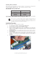
Installing the Motherboard
Please make sure that the USB cable has the same pin assignment as
indicatged above. A different pin assignment may cause damage or system
hang-up.
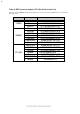
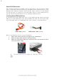
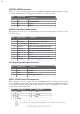
USB3~USB4: Front Panel USB connectors
The motherboard has four USB ports installed on the rear edge I/O port array. Additionally,
some computer cases have USB ports at the front of the case. If you have this kind of case,
use the onboard USB connectors to connect the front-mounted ports to the motherboard.
1 USBPWR Front Panel USB Power
2 USBPWR Front Panel USB Power
3 USB_FP_P0- USB Port 0 Negative Signal
4 USB_FP_P1- USB Port 1 Negative Signal
5 USB_FP_P0+ USB Port 0 Positive Signal
6 USB_FP_P1+ USB Port 1 Positive Signal
7 GND Ground
8 GND Ground
9 Key No pin
10 USB_FP_OC0 Overcurrent signal
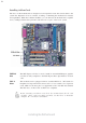
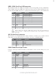
AUX_IN: Auxiliary In connector
This connector is an additional line-in audio connector. It allows you to attach a line-in
cable when your rear line-in jack is set as line out port for 4-channel function.
COM2: Onboard serial port header
Connect a serial port extension bracket to this header to add a second serial port to your
system.
Pin Signal Name
Function
1 AUX_L AXU In left channel
2 GND Ground
3 GND Ground
4 AUX_R AXU In right channel
Pin Signal Name
Function
1 NDCDB Data carry detect
2 NSINB Serial Data In
3 NSOUTB Serail Data Out
4 NDTRB Data terminal ready
5 GND Ground
6 NDSRB Date set ready
7 NRTSB Request to send
8 NCTSB Clear to send
9 NRIB Ring Indicator
10 KEY Key
Pin Signal Name
Function